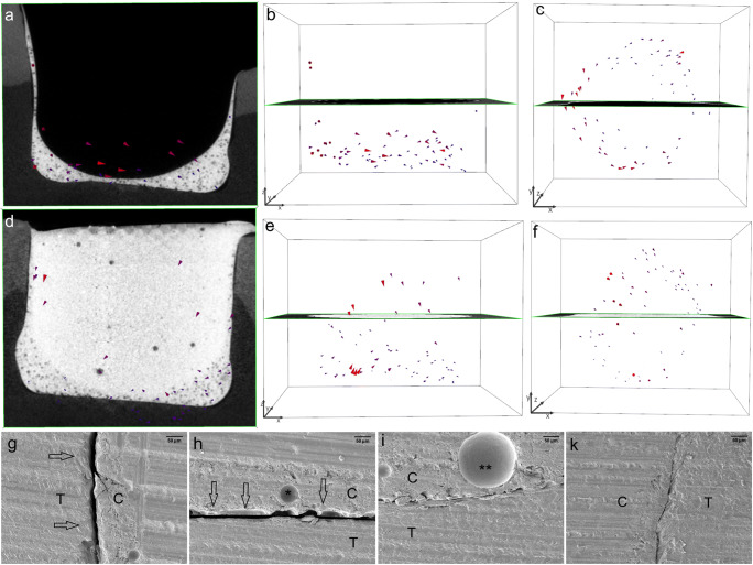
Fig. 5.
In gp2-fl/TEF + TBF, the shrinkage vectors of the Tetric EvoFlow Bulk Fill (TEF) flowable liner are medium-sized and point toward the right side of the image (a); the radiographic x-plane is located in the background. The unobstructed view of the shrinkage vector field shows the disorder of the shrinkage vectors (b), which appear as a swirl from the top view (c). The layer of flowable liner is conical in shape as the surface tension of the composite drives the material toward the state requiring the least energy. The bulk application of Tetric EvoCeram Bulk Fill (TBF) yields larger shrinkage vectors pointing downward, whereas the lower part, corresponding to the flowable liner, displays smaller shrinkage vectors away from the cavity floor (d, e). From the top view, shrinkage vectors can be observed toward one side of the restoration (f). The shrinkage vectors are magnified by a factor of 10 for better visualization. The SEM images (at × 200 magnification) of one margin (g) and one area of the cavity floor (h) show detachment (arrows) of the restoration from the cavity boundaries, whereas the other areas (i, k) show intimate contact between the restoration and the tooth. The star (*) represents the area of a glass filler, and two stars (**) represent the area of an air bubble within the restoration

