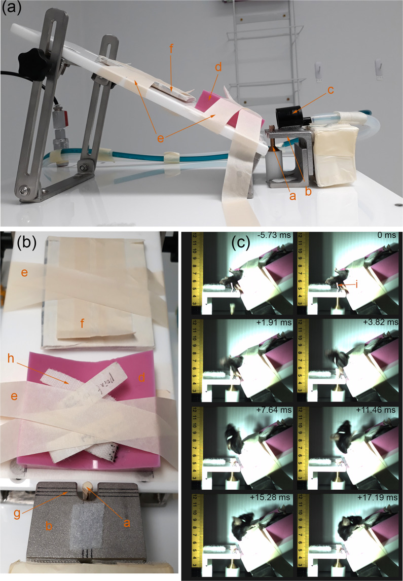
Fig. 2.
Schematic of the impactor device. (a) Side view of the body and head support of the device with the piston at the highest (impact) position, (b) Top view the body and head support of the device with the piston at the highest (impact) position and the nose cone (orange c) removed for clarity, (c) frame-by-frame breakdown of high-speed camera footage of mouse cadaver’s head impacted at piston velocity = 5.2 m/s from just before the start of the impact and the furthest head position. (Orange letters) a = piston and brass impactor tipped with neoprene rubber, b = head support plate, c = isoflurane anaesthesia nose cone, (d) = non-slip silicone body support, (e) = masking tape restraints, (f) = tail restraint, g = “crosshairs” to “aim” the impactor at head position marker (i), h = Velcro body restraint straps, i = 1 mm thick masking tape indicating position to be centred around (g) crosshair. Figures and legends previously included in15.

