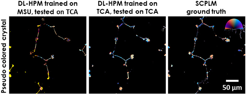
Figure 6.
Comparison of two different deep neural networks for imaging TCA samples using DL-HPM. The first network is trained with only MSU samples, and the second network is trained through transfer learning from the original MSU network with a training data set containing TCA samples. Color bar: from left to top to right, represents π, π/2, 0 Rad in the orientation channel. Retardance is represented by the distance from the center of the color bar, ranging from 0 to 0.4.

