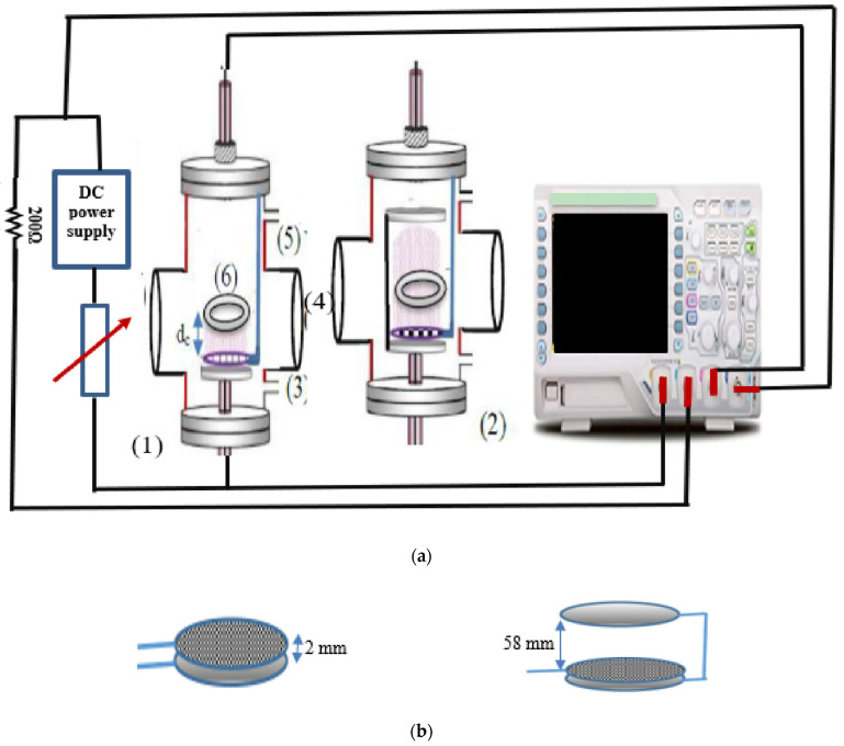
Figure 1.
(a) Schematic diagram of the experimental set-up of the evacuated chamber containing (1) the OMSE reactor, (2) the OMTSE reactor, (3) gas inlet, (4) window, (5) rotary pump, and (6) sample holder over the cathode fall region dc. (b) System 1, OMSE reactor (left), and System 2, OMTSE reactor (right).

