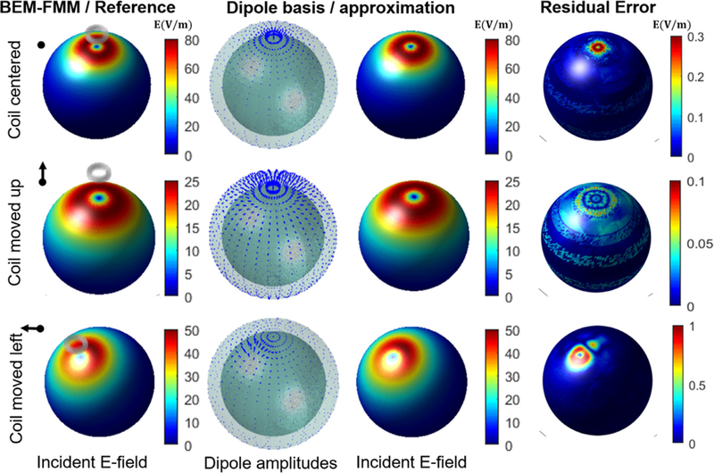
Fig. 2.
The incident E-field of a circular TMS coil on a spherical surface calculated by the BEM-FMM and the corresponding dipole approximation. Each row shows the results as the position of the coil changes. The amplitude of the dipole basis set changes according to the coil position in the expected fashion. The residual error shows the difference in the E-field amplitude between the full BEM-FMM and the dipole approximation. Note the different scales in the error bars of the residual plots.

