
Extended Data Fig. 4. Estimated polar and azimuth angle errors for orientation recovery at S/N = 10.
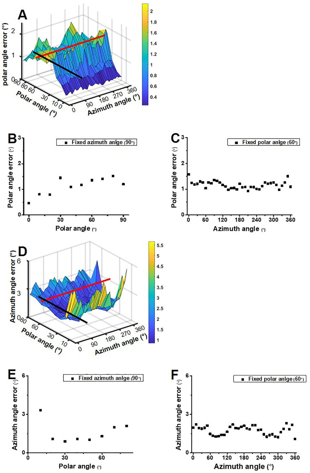
(A) Estimated polar errors for orientation with various combinations of the azimuth angle and polar angle at S/N = 10. (B) The cross section along the black line in (A) shows the polar angle errors with various polar angles and a fixed azimuth angle of 90°. (C) The cross section along the red line in (A) represents the polar angle errors with various azimuth angles and a fixed polar angle of 60°. (D) Estimated azimuth errors for orientation with various combinations of the azimuth angle and polar angle at S/N = 10. (E) The cross section along the black line in (D) shows the azimuth angle errors with various polar angles and a fixed azimuth angle of 90°. (F) The cross section along the red line in (D) represents the azimuth angle errors with various azimuth angles and a fixed polar angle of 60°.