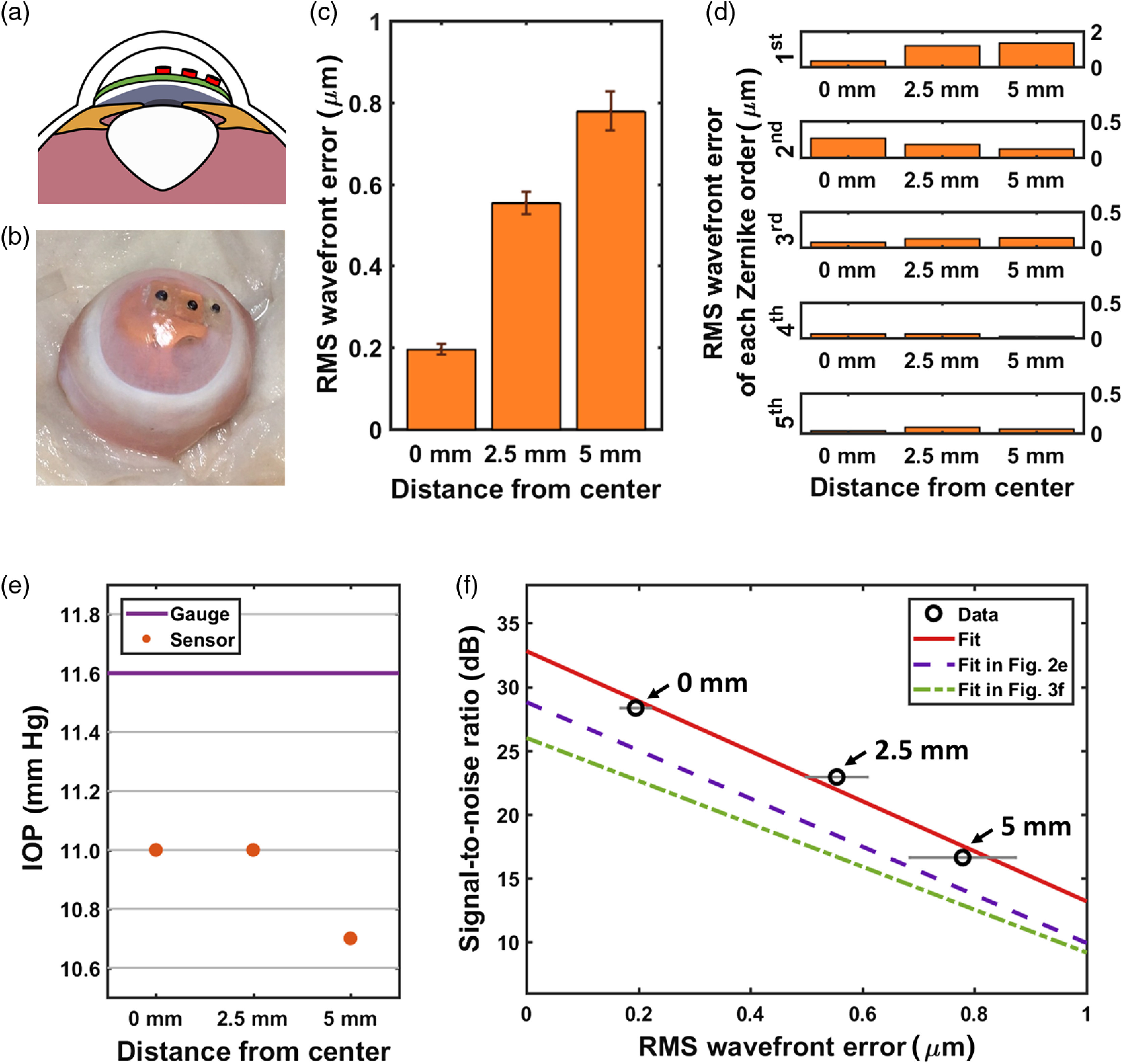
Fig. 4.

Measurements using three IOP sensors implanted at three different locations. (a) A cross-sectional illustration of the IOP sensors placed at three different locations. (b) A photograph of the three IOP sensors implanted inside the anterior chamber of an ex vivo rabbit eye. (c) The rms-wavefront error of the readout from each implanted IOP sensor. (d) rms-wavefront error of each Zernike order at different locations. (e) Comparison between the readings from the digital pressure gauge and the implanted IOP sensors. (f) SNR of the optical spectra of the implanted IOP sensors plotted against the rms-wavefront error.
