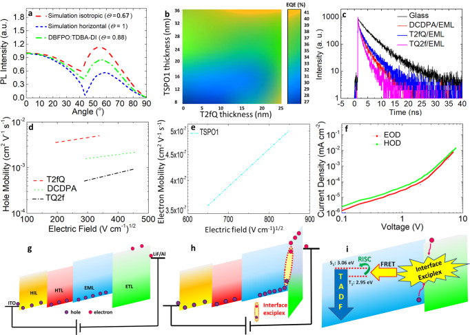
Fig. 4. Proposed operation mechanism.
a Dependence of polarized PL intensity on the emission angle and b simulations for the thickness optimization of TSPO1 and T2fQ ETM and HTM. c TRPL decay curves of the EML on glass, DCPPA, T2fQ, and TQ2f films. d Variation of hole mobility vs. the applied field for the three different HTMs used in this study. e Variation of electron mobility on the applied field of the TSPO1 ETM. f Current densities measured in hole-only (ITO/NPD/TQ2f/DBFPO 20%-TDBA-DI/NPD/Al) and electron-only (ITO/TSPO1/DBFPO 20%-TDBA-DI/TSPO1/LiF/Al) devices. Schematic response of an ITO/NPD/T2fQ/EML/ETL/LiF/Al device under forward applied bias. g The electric field (slope of the energy levels) is evenly distributed across the device. Holes and electrons are injected from the anode and cathode contact, respectively, and transported through the HTL and ETL towards the EML. Due to the large difference in hole and electron mobilities of the HTM and ETM, respectively, holes are reaching the EML before electrons are transported within the ETL. h, i Holes reaching and start building up at the EML/ETL interface screen the electric field to the ETL. The redistribution of the electric field into the ETL accelerates electron injection/transport and electrons reach the EML/ETL interface where they subsequently form interfacial exciplexes with holes in the DBFPO layer. Interface exciplex confines excitons and transfers them to the emitter.

