
Fig. 3. Illustrative example of a polarization-analyzing hologram.
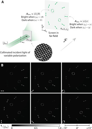
(A) When illuminated with collimated laser light, a suitably designed metasurface hologram implements a far-field in which light is directed on the basis of its incident polarization state. In this particular example, the hologram is designed to produce a pattern of illustrations of different polarization states. Each drawing acts as an “analyzer” for its depicted polarization state. For instance, the drawing of x-polarized light (horizontal line) is bright when ∣j〉in = ∣x〉 and dark when ∣j〉in = ∣y〉; this part of the far-field implements the Jones matrix Ades = ∣x〉〈x∣. SEM scale bar, 1 μm. (B) The far-field measured on a digital image sensor reflects this desired behavior for six incident polarization states (∣j〉in is denoted in white at the lower left of each image). The right scale bar shows the cone angle subtended by the far-field, while a color bar denotes the image intensity.