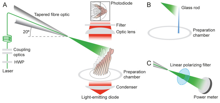
Appendix 1—figure 2. Experimental configuration.
The schematic drawing shows the arrangement of the main components in the experimental apparatus. (A) The laser beam of 561 nm wavelength (green line) traverses the half-wave plate (HWP) and is coupled to the tapered optical fiber. The fiber's distal end with the microlens is approximated to the experimental preparation under a microscope. Illumination from a light-emitting diode with a central wavelength of 660 nm (red) is focused by a condenser onto a hair bundle, which is imaged onto a dual photodiode with a 60X objective lens of numerical aperture of 1.0. A dichroic mirror blocks 562 nm laser light but it passes the light coming from the light-emitting diode. (B) In control experiments, a glass rod (blue triangle) of stiffness comparable to that of a bullfrog’s hair bundle is mounted vertically in the experimental chamber. The laser light (green triangle) deflects the rod, whose motion can be measured with the system in panel A. (C) To orient the plane of polarization of light with the long axis of the stereocilia, light from the tapered optical fiber is passed through a linear polarizing filter and its intensity is measured with a power meter. The maximal power is detected when the polarization plane is aligned with the transmission direction of the polarizing filter.

