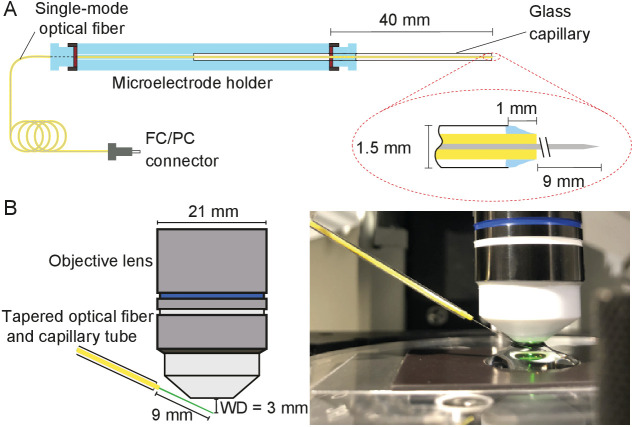
Figure 10. Positioning fiber under an objective lens using a custom-made holder.
(A) Holder for the tapered optical fiber. The schematic drawing portrays a tapered optical fiber inserted in the mount constructed from a microelectrode holder and a glass capillary, from which the fiber’s distal tip protrudes 10 mm. The coiled optical fiber's inner core is depicted in gray inside the yellow jacket. As seen in the inset, the space between the glass capillary and the yellow jacket that protrudes 1 mm past the capillary’s tip is packed with vacuum grease (light blue). The distal end of the fiber is terminated with an FC/PC connector. Positioning of a fiber under an objective lens. (B) A schematic drawing (left) shows the length of the glass capillary that protrudes from the fiber-holder relative to the objective lens of working distance (WD) 3 mm. The photograph (right) shows the tapered optical fiber, objective lens of the microscope, and preparation chamber in an experiment.

