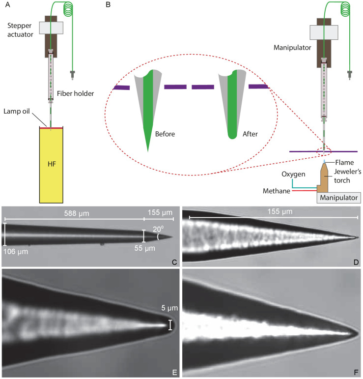
Figure 8. Preparation of a tapered optical fiber.
(A) A schematic diagram depicts the process of reducing the optical fiber's diameter by chemical etching. The tapered optical fiber is attached to the shaft of a linear actuator and lowered into a tube of hydrofluoric acid (HF) topped with a thin layer of lamp oil (kerosene). The convergence angle of the fiber’s tip is determined by the rate at which the tip is extracted from the acid. (B) A schematic diagram depicts the apparatus for creating a hemispherical lens at the fiber’s tip. With the aid of a three-axis micromanipulator, the fiber’s tip is inserted through a hole less than in diameter in a horizontally mounted metal plate (purple line). The nozzle of a jeweler’s torch is aligned with the optical fiber by means of a second micromanipulator. Careful adjustment of the flow of oxygen and methane yields a flame about 0.5 mm in height. Under microscopic observation, the flame is raised until the fiber’s tip melts, whereupon the fiber is immediately retracted. (C) An image of a fiber’s tip after chemical etching with 48% hydrofluoric acid and before polishing shows a slow taper over 588 μm followed by a steep taper over the final 155 μm. (D) At a higher magnification, the tapered but unpolished tip displays a cone angle of about 20°. (E) A high-magnification image depicts a polished tip with a relatively large hemispherical lens. (F) Another polished tip ends in a narrower lens.

