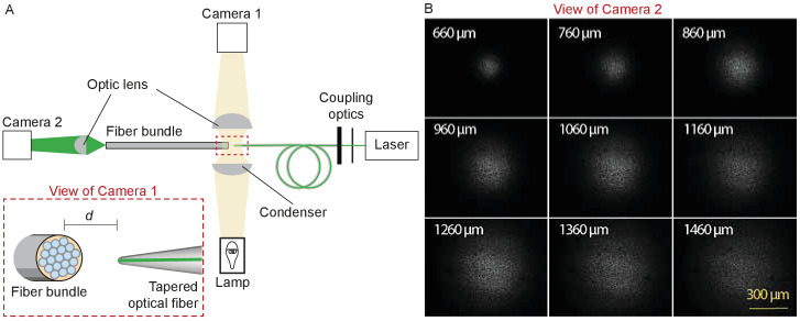
Figure 9. Characterization of the light spot produced by a polished fiber.
(A) A schematic diagram depicts the apparatus for characterization of a fiber’s output. During observation by camera one attached to the microscope, the tapered optical fiber is coupled to the laser and brought near the transverse surface of a fiber bundle (IGN-8/30, Sumitomo Electric, Japan). The view through camera 1, with the fiber tip pointing at one end of the fiber bundle a distance d away, is schematized in the inset. The fiber bundle has 30,000 inner cores, each 2 μm in diameter and with a center-to-center spacing of 4 μm. The distal end of the bundle is imaged by camera two at a magnification of 11.6X. (B) Images of the output, as captured with camera 2, show the divergence of the light beam as the tapered optical fiber is brought approximately 660 μm from the bundle and retracted by intervals of 100 μm.

