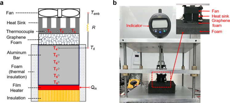
Fig. 4. Setup of the proof-of-concept experiment in an environmental chamber.
a Schematic and b Photo of the performance test set-up. A film heater is used to mimic a device and placed on a block of hard polymer foam insulation to minimize heat dissipation through the baseplate. An aluminum bar (1” × 1” in cross-section and 0.8” tall) is placed above the heater with 6 thermocouples to quantify the heat flow. The thickness of the graphene foam, inserted between the aluminum bar and the heat sink, can be controlled by moving the middle plate shown in panel b. An indicator measures the movement of the middle plate and is related to the thickness of graphene foam. The temperature of the top thermocouple (T4), which is 0.1” from the surface, is taken as the device temperature for the calculation of thermal regulation to remove the effect of the added aluminum bar. Three thermocouples additional are distributed within the base of heat sink. Another thermocouple, floating in the air, measures the ambient temperature. The whole system is contained within an environmental chamber where the ambient temperature can be adjusted from 0° to 30 °C.

