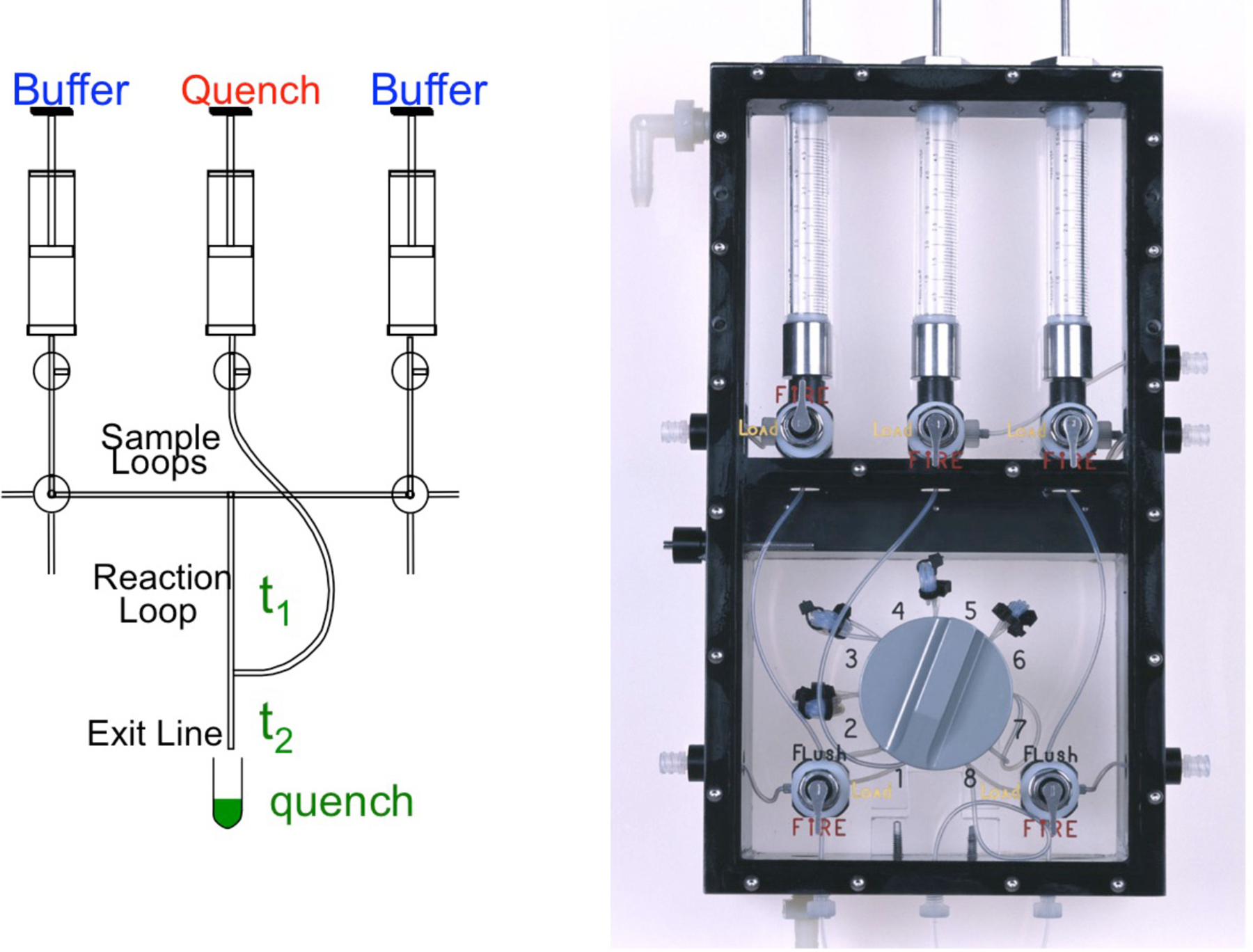
Figure 3.

Rapid chemical-quench-flow apparatus. We show the schematic (left) and photograph of the syringe/valve chamber of a KinTek RQF-3 instrument. The two samples are loaded into the left and right hand Sample Loops, then after changing the valve position, a computer controlled motor drives the syringes containing Buffer to force the reactants to mix. Reaction occurs as the mixed samples flow through the Reaction Loop and is terminated by mixing with solution from the Quench syringe. The sample is then expelled into a collection tube so that it can be analyzed to determine the concentration of product for a particular time point. The time of reaction is varied by changing the length of the Reaction Loop using the 8-way valve shown in the photograph at the right, and by slightly altering the flow rate.
