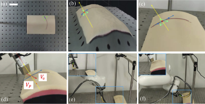
Fig. 5.
Depth camera based initial probe placement. (a) image of target area with depth information overlaid, (b) 3D surface rendering of target area (c) normal camera image of target area, (d) zoomed view of the relative position between probe and target sample, (e) probe at original position, and (f) probe at the specific pose. (blue vector indicates the scan path and the yellow vector indicates the surface normal vector.) (scale bar: 50 mm).

