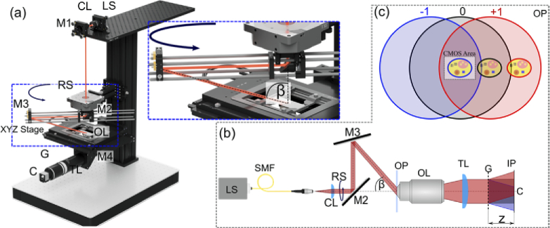
Fig. 1.
Total shear tomographic system. (a-b) schematic of the optical setup: LS – light source, SMF – single mode fiber, CL – collimating lens, M – mirror, RS – rotation stage, OP – object plane, OL – objective lens, TL – tube lens, G – diffraction grating, C – CMOS sensor, IP – image plane (c) illustration of the image capture configuration. −1st, 0th and +1st diffraction orders are represented with blue, black and red colors, respectively. The CMOS area contains the object image carried by −1st diffraction order (indicated with the blue stroke) and flat area of the 0th and +1st orders.

