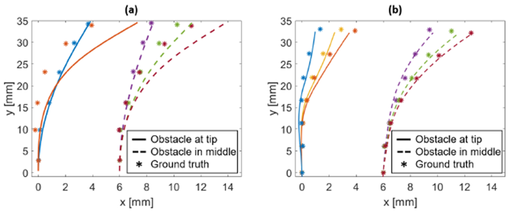
Fig. 9.

CDM shape reconstruction when interacting with obstacles using (a) the FBG-based sensor and (b) the ROGUE-based sensor. In both cases, the asterisk markers show the ground truth, obtained by the pair of stereo cameras. The solid lines show the reconstructed shape when the obstacle is placed at the tip of the CDM, while the dashed line correspond to the shape when the obstacle is placed in the middle of the CDM. The latter is translated by 6 mm in the graphs to avoid superposition of the plots.
