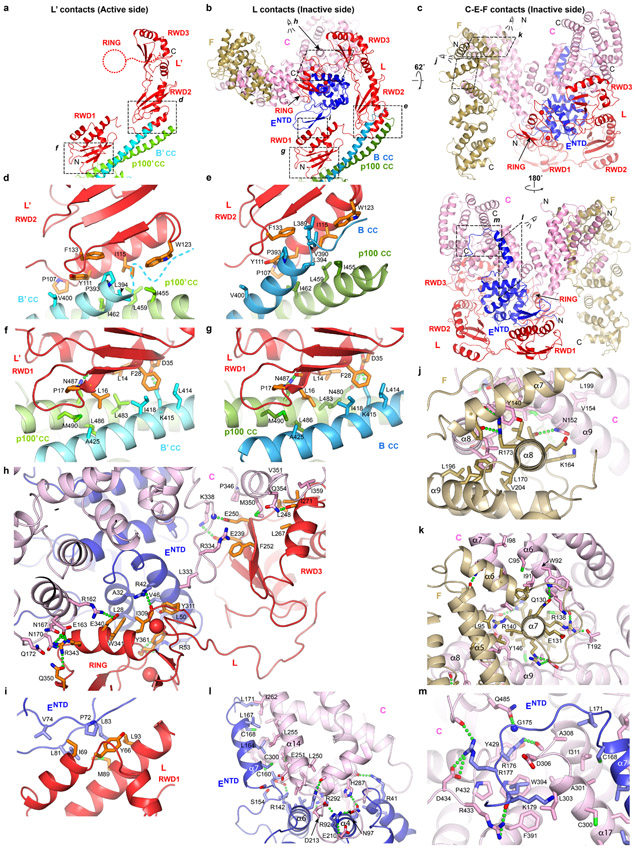
Extended Data Fig. 4. Inter-subunit interactions of FANCL and of FANCC-FANCENTD-FANCF.
a-b, Overall views of FANCL at the active-side (a) and inactive-side (b) of the apo-Core complex also showing their Core-contacts. View in b is oriented as in a by superposition on the RWD1 domain. Dashed red circle indicates that the FANCL’ RING domain is poorly ordered in the apo-Core complex structure. The regions that panels d-i zoom into are delineated by dashed rectangles. The N- and C-termini of FANCL/FANCL’ are labeled.
c, Top, the FANCC-FANCENTD-FANCF subcomplex also showing FANCL to which it makes its majority of contacts. View is rotated by 62° about the horizontal axis relative to b. Bottom, view rotated by 180° about the vertical axis. The regions that panels j-m zoom into are delineated by dashed rectangles looking into the plane of the figure, or by slanted rectangles with arrows indicating the direction of the view. The N- and C-termini of FANCC, FANCENTD and FANCF are labeled.
d-g, Close-up views showing interactions of FANCB-FAAP100 coiled coil with the FANCL RWD2 domain at the active (d) and inactive (e) sides of the Core complex, with the FANCL RWD1 domain at the active (f) and inactive (g) sides of the Core complex.
h-i, Close-up views of the contacts FANCC and FANCENTD make to the FANCL RWD1, RWD3 and RING domains at the inactive side. The helix α18 of FANCC is not shown for clarity in h.
j-m, Close-up views of the contacts between FANCC and FANCF (j, k), and between FANCC and FANCENTD (l, m). Subunits are colored as in Figure 1a. Only side chains involved in intermolecular interactions are shown. Green dotted lines indicate hydrogen bond contacts. Dashed colored curves indicate disordered regions. The interactions shown in panels d to m are described in Supplementary Note 3.

