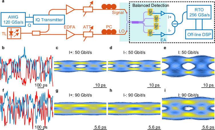
Fig. 4. Balanced detection testing.
a Measurement setup for the balanced detection. AWG: arbitrary waveform generator, TL: tunable laser, EDFA: erbium-doped fiber amplifier, PC: polarization controller, ATT: optical attenuator, EA: electric amplifier, RTO: real-time oscilloscope. b, f The real signal waveforms of 50 Gbit/s (b) and 90 Gbit/s (f) BPSK signals (blue line stands for I + branch and red line stands for I− branch). c–e Eye diagrams of I + branch (c), I− branch (d), and balanced detection (e) for 50 Gbit/s BPSK signal. g–i Eye diagrams of I + branch (g), I− branch (h), and balanced detection (i) for 90 Gbit/s BPSK signal.

