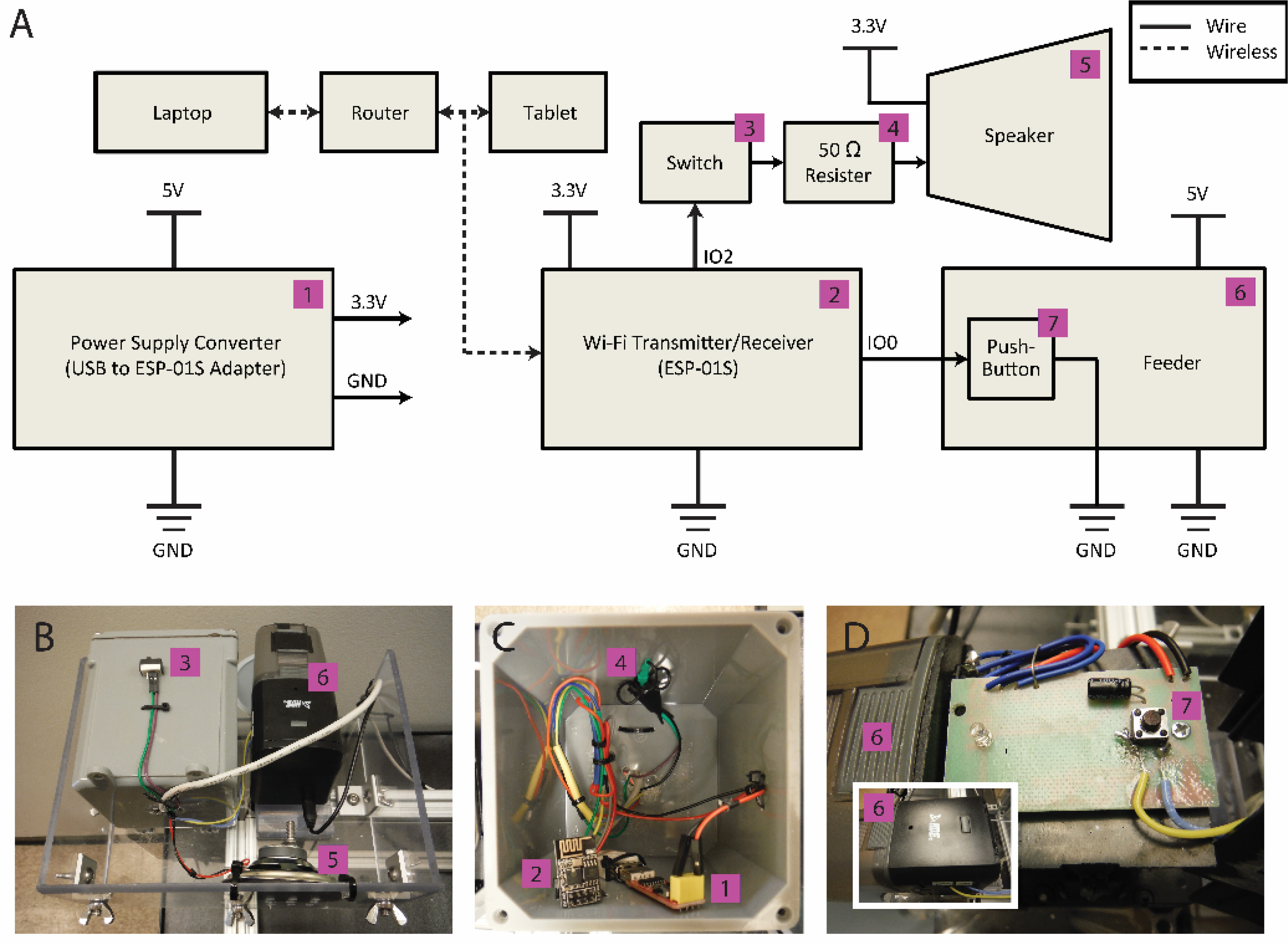
Figure 3:

Electrical schematic. (A) The entire ACTS system is driven by custom MATLAB code running on a laptop. The laptop communicates via Wi-Fi through a router to both the tablet and the Wi-Fi transmitter/receiver (ESP-01S). The Wi-Fi transmitter/receiver is powered by a power supply converter (USB to ESP-01S Adapter) which is plugged into a standard wall power outlet via a USB cable and wall adapter. The IO2 port of the Wi-Fi transmitter/receiver is wired to the speaker via a switch and a 50 Ω resister. The switch is necessary to disconnect the Wi-Fi transmitter/receiver from the speaker during startup and the resister is necessary to improve impedance matching. The speaker is powered by the power supply converter. The IO0 port of the Wi-Fi transmitter/receiver is wired directly to the pushbutton of the feeder. The feeder is plugged into a standard wall power outlet via a USB cable and wall adapter. (B) A box mounted on the back of the structure contains the feeder, speaker, and electrical box, on which is affixed the speaker switch. (C) The power supply convertor, Wi-Fi transmitter/receiver, and resister are all stationed inside the electrical box with plastic cable ties. Wires were given enough length to allow the electronics to be manipulated by hand outside of the electrical box as needed. (D) The feeder shown with its casing both removed and intact (inset picture). Wires were soldered to pins of the pushbutton to allow for wireless operation: The yellow wire delivers the signal from the Wi-Fi transmitter/receiver and the blue wire is tied to ground. The jackets of the wires were glued to the electrical board of the feeder to reduce risk of mechanical stress on the solder points. The wires were routed out of holes drilled in the casing of the feeder to allow integration with the other electronics.
