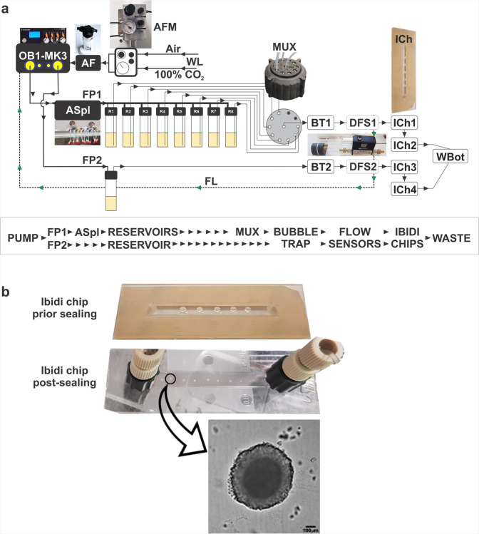
Fig. 1. Microfluidic platform design.
a Components of the microfludic set up. Air and CO2 from the wall lines (WL) are mixed in airflow mixer (AFM) and passed through air filter (AF) before reaching the pump (OB1-MK3). Flow path 1 (FP1) with air splitter (ASpl) shows eight outlets connected to the reservoirs with specific drug concentrations. Time and flow rate of the reservoir content are regulated by the distributor (MUX) and piezo pump (OB1-MK3). The FP1 continues to a bubble trapper (BT) and a digital flow sensor (DFS) into 2 chained Ibidi chips (ICh 1,2) and finaly to the waste bottle (WBot). Flow path 2 (FP2) for mock treated spheroids is represented by single reservoir and the two chained Ibidi chips (ICh 3,4). A feedback loop (FL) connects each digital sensor (DFS) to the OB1-MK3 pump to maintain desired flow rate. b Photograph of the Ibidi Luer chip with 8 Matrigel encapsulated spheroids, and brighfield microscopic image of SW620 spheroid after 7 days of continuous media flow. Scalebar = 100 µm.

