Figure 1.

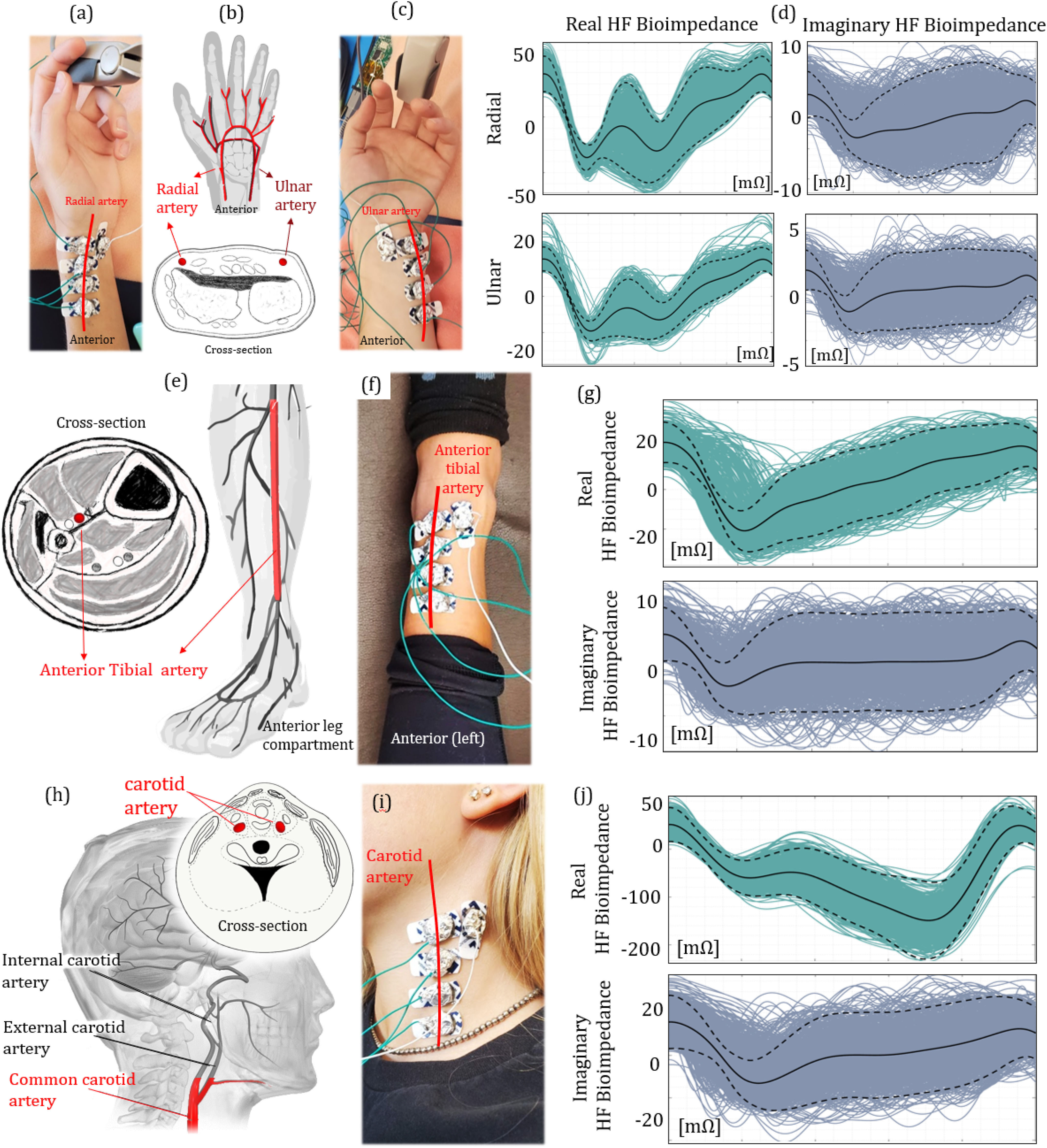
The bioimpedance signal analysis at different arteries. (a), (c) Electrode placement at the radial (left) and ulnar (right) arteries. (b) Cross-sectional view of the wrist, indicating the locations of both radial and ulnar arteries. (d) Real (left) and imaginary (right) ensemble HF bioimpedance signals obtained from the radial (top) and ulnar (bottom) arteries, showing the repeated quasiperiodic patterns. (e) The anterior leg anatomy, indicating the location of the anterior tibial artery. (f) Electrode placement at the anterior tibial artery. (g) Real (top) and imaginary (bottom) ensemble HF bioimpedance signals measured at the anterior tibial artery. The peak-to-peak amplitude of the HF bioimpedance signal is lower than that of radial artery under the same AC current injection due to hindered position of the tibial artery. (h) The cross-sectional and side view of the human neck with the carotid artery location. The red marked section is used to capture the bioimpedance signal. (i) Electrode placement at the common carotid artery. (j) Real (top) and imaginary (bottom) ensemble HF bioimpedance signals captured from the common carotid artery showing different morphology compared with other measured arteries, due to the late systolic carotid blood flow.
