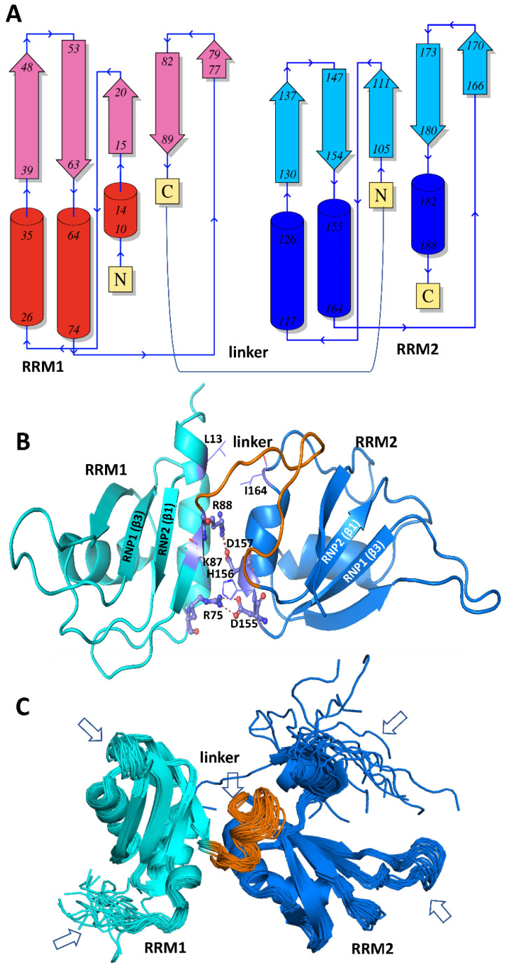
Figure 5.
hnRNP A1 RRM structures. (A) The secondary structure topology diagram describes the β1α1β2β3α2β4 arrangements of both RRM1 and RRM2 in A1: four antiparallel β-sheets and two α helices as numbered in the figure. (B) A cartoon representation of the 3D structure of A1 RRMs (based on PDB: 1UP1), where RRM1 is shown in cyan and RRM2 in blue. The linker connecting the two RRMs is shown in orange. The key salt bridge interactions (shown as ball-and-stick representations) and hydrophobic contacts (residues shown in line format) at the interface of tandem RRMs are shown. The β-sheets encompassing RNP1 (β3) and RNP2 (β1) motifs in both the RRMs are marked in the structure. (C) A structural ensemble of 20 A1 RRM conformers (PDB code: 2LYV) are shown, and the flexible regions in the structures are marked with arrows.

