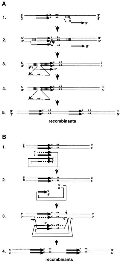
FIG. 9.
Models for tandem element formation. The models illustrate the formation of class III recombination products (Fig. 8), although the same models can also generate class I and class II products. Class I and II products are formed, depending on the site of strand invasion (A) or the extent of recession (B). A single asterisk indicates the BamHI mutation; two asterisks indicate the HindIII mutation. Thick arrows represent LTRs; thin dotted lines represent newly synthesized DNA; dashed thick arrows represent recessed LTR sequences. (A) Step 1. The 3′ end of partial-minus-strand Ty5 cDNA (single stranded) invades the substrate. Step 2. branch migration and strand displacement continue through the 5′ LTR. The Holliday junction is cleaved (small arrowhead). Step 3. The LTR at the 5′ end of the invading cDNA displaces the newly synthesized LTR at the 3′ end. This forms a looped intermediate. The 3′ OH at the site of the Holliday junction is ligated to the 5′ end of the cDNA. The strand with the free 5′ end, released from Holliday junction cleavage, is trimmed and ligated (small arrowhead). Step 4. The mismatch repair system cleaves the top strand of the mismatched region. DNA repair is carried out, with the bottom strand as a template, followed by ligation. Step 5. Recombination products are formed, with markers in both the 5′ and 3′ elements. (B) Step 1. The cDNA is recessed beyond the region containing the two markers. Step 2. The 3′ end of the cDNA invades the substrate, and DNA synthesis repairs the gap. Step 3. The Holliday structure is resolved; the small arrows indicate the sites of cleavage. Step 4. Recombination products are formed, with markers in both elements.

