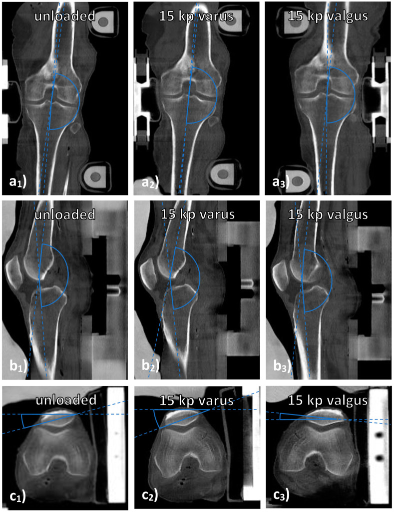
Figure 1.
Measurements of joint alignment on CT images. Visualized are coronal (a), sagittal (b), and axial (c) reconstructions of a representative knee joint under various loading conditions, i.e., unloaded (a1–c1), under 15 kp varus loading (a2–c2) and under 15 kp valgus loading (a3–a3). “Joint deviation” was determined on mid-coronal images as the lateral angle between the femoral and tibial shafts (a). “Joint extension” was determined on mid-sagittal images as the popliteal angle between the femoral and tibial shafts (b). “Joint rotation” was determined on the axial images that demonstrated the largest diameter of the patella by relating the trans-patellar line (through the outer corners of the patella) to the horizontal line (c). By convention, external rotation was indicated by positive angles and internal rotation by negative angles.

