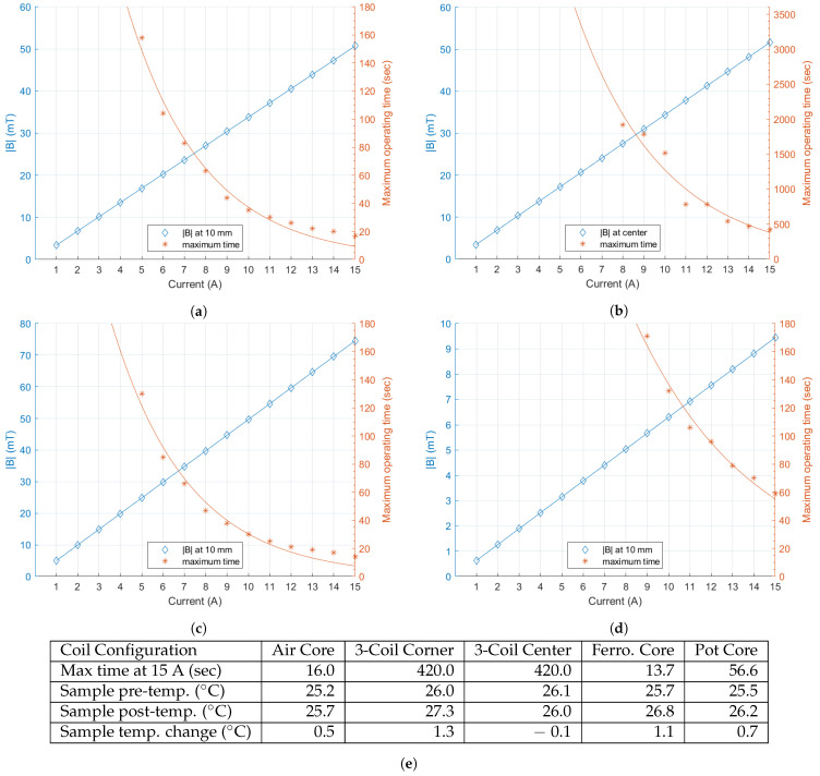
Figure 6.
|B| at 10 mm from the coil or the center for the three-coil system, shown on the left axis for a range of 1 to 15 Amperes for the (a) air core coil; (b) three-coil system; (c) ferromagnetic core coil; and (d) pot core coil. In addition, the maximum operating time along the right axis for the same conditions is shown. Operating times are shown only up to one hour for the three-coil system and three minutes for the remaining geometries; (e) summary of the device operating times and sample temperatures for each coil design.

