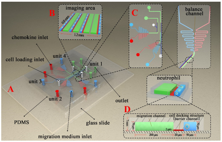
Figure 1.
Schematic diagram of the F4-Chip used for cell chemotaxis research. (A) The isometric view of F4-Chip. (B) Enlarged view of the imaging area. (C) Enlarged view of unit 3 and unit 4. Each unit has its specific cell loading inlet, reagent inlet, and outlet. In addition, each unit has a balance channel to balance the pressure between the chemokine inlet and migration medium inlet. (D) The enlarged cell docking structure.

