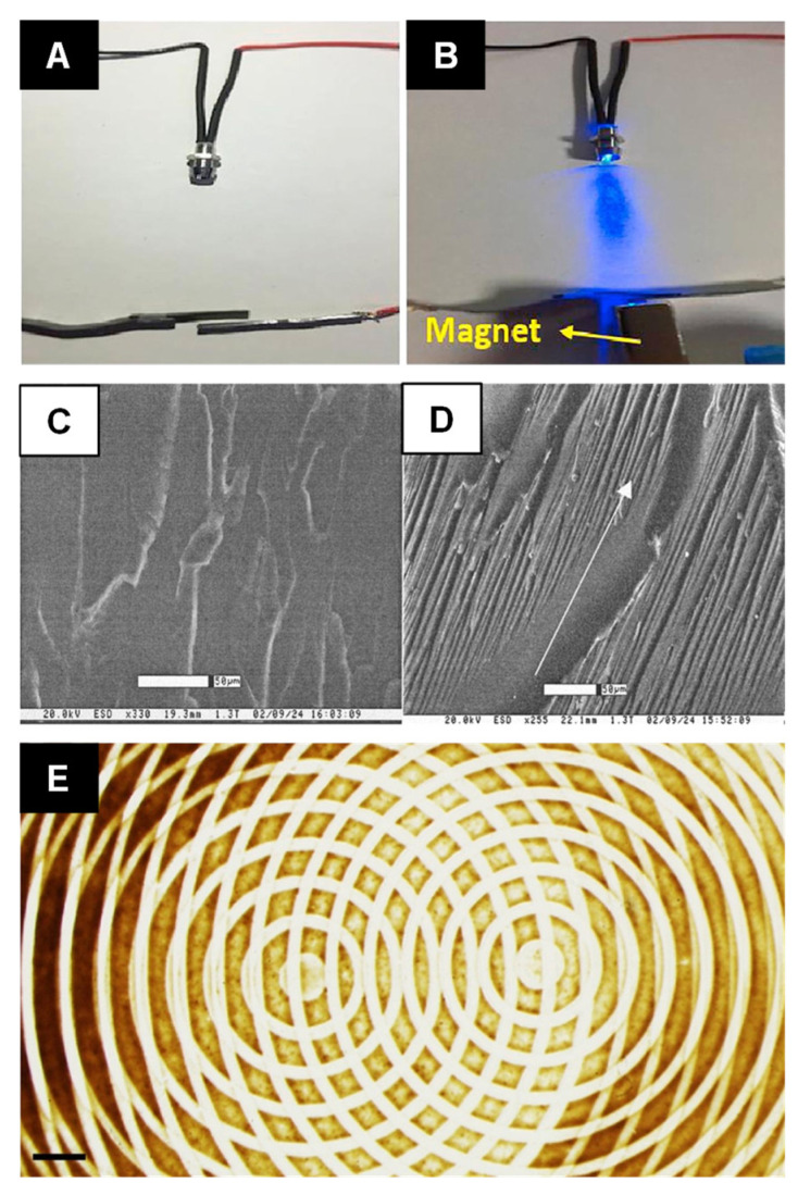
Figure 4.
A nanocomposite magnetic switch: (A) a gap between an aligned CNT coated composite and a nonmagnetic Pb is (B) closed when a magnet is placed underneath the Pb sheet, which lights an LED. Reprinted with permission from [112]. Copyright 2019 Elsevier. Environmental scanning electron microscopy images show the morphology of an epoxy composite sample processed at (C) no applied magnetic field and (D) at 15 T. The arrow represents the direction of the corresponding magnetic field. Reprinted with permission from [114]. Copyright 2004 John Wiley and Sons. (E) A complex pattern formed in a composite by the superposition of two separate magnetic fields. Reprinted with permission from [115]. Copyright 2017 Springer Nature.

