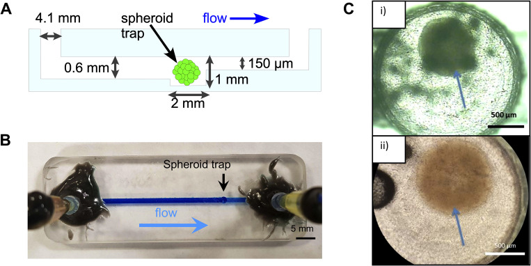
FIG. 1.
Flow 1 device design and validation. (a) Schematic side view of the flow 1 microfluidic chip showing the main components and key dimensions, as well as direction of flow. 4.1 mm wide inlet and outlet ports are placed at each end of the chip. A 1.5 mm wide channel runs from the inlet to the outlet end (55 mm long). A “trap” is situated 41.5 mm downstream from the inlet featuring a 2 mm chamber to harbor the spheroid. The channel upstream of the spheroid trap is 0.6 mm deep, and downstream of the trap it constricts to 150 μm. The constriction in channel size prevents the spheroid from flowing out of the middle chamber and creates the trap. (b) Photograph of the flow 1 device fabricated from glass. The tubing for media flow is shown glued to the inlet and outlet. Brilliant blue dye flowing through the chip demonstrates the location of the channel and direction of flow. (c) Microscope images of spheroids (indicated by the arrows) inside the chamber on-chip indicating successful incorporation: (i) U-87 MG spheroid seeded at 3.5 × 10⁴ cells And (ii) U-87 MG spheroid seeded at 2.5 × 10⁴ cells.

