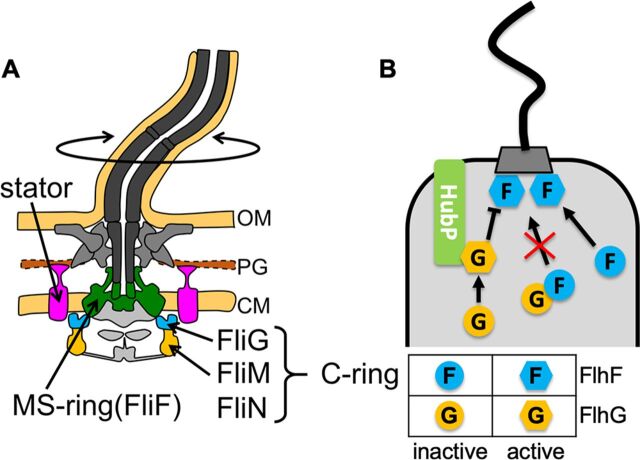
FIG 1.
(A) Schematic drawing of the flagellum in Vibrio. The basal part of the flagellar motor consists of the transmembrane MS-ring and the cytoplasmic C-ring. The MS-ring is shown in green. The C-ring component FliG is shown in cyan, and FliM/FliN is in orange. The stator complexes are shown in pink. CM, cytoplasmic membrane; PG, peptidoglycan layer; OM, outer membrane. (B) Schematic drawing of flagellar number and location control by FlhF and FlhG in Vibrio. An “F” in circles or hexagons represents inactive and active FlhF, respectively. A “G” in circles or hexagons represents inactive and active FlhG, respectively. HubP is shown in light green.

