
Figure 2. CryoEM structure of S‐Enas.
CryoEM analysis of S‐Enas isolated from B. cereus NVH 0075‐95.
-
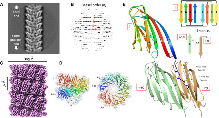
A, B(A) Representative 2D class average of 300 × 300 pixel boxes covering ex vivo S‐Enas and (B) the corresponding power spectrum of the 2D class. The Bessel orders used to derive helical symmetry are indicated.
-
CReconstituted cryoEM electron potential map of ex vivo S‐Ena (3.2 Å resolution).
-
DSide and top view of a single helical turn of the de novo‐built 3D model of S‐Ena shown in ribbon representation and molecular surface. Adjacent Ena subunits are labeled i, i‐1, i‐2 to i‐10 (colored red to blue), where subunits i and i‐10 represent the upper and lower subunit in a single helical turn. Based on the orientation and low‐resolution features of 2D classes obtained on spore‐associated S‐Ena (Fig 1), subunits i and i‐10 would be oriented distal and proximal to the spore body, respectively.
-
ERibbon representation and topology diagram of the S‐Ena1B subunit (blue to red rainbow from N‐ to C‐terminus). The eight β‐strands making up the S‐Ena core domain are labeled B to I from N‐ to C‐terminus. The first 15 residues form an N‐terminal connector (Ntc) that for a subunit i, is in interaction with subunits i‐9 (sand) and i‐10 (green) through disulfide cross‐linking.