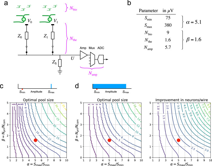
Fig. 2. Pooling of signal and noise.
a An idealized circuit for two electrodes connected to a common wire along with downstream components of the signal chain, such as the amplifier, multiplexer, and digitizer. Z0, Z1: total impedance for electrodes 0 and 1, with contributions from the metal/bath interface and the external bath. ZS: shunt impedance at the amplifier input. Noise sources include biological noise from distant neurons (Nbio); thermal noise from the electrode impedance (Nthe), and common electronic noise from the amplifier and downstream components (Namp). b Numerical values of the relevant parameters, derived from experiments or the literature (sections Experiments and Simulations). c, d The optimal electrode pool under different assumptions about the spike amplitude distribution (top insets). The contour plots show the optimal pool size and the enhancement of the neuron/wire ratio as a function of the parameters α— the ratio of largest to smallest sortable spike signals—and β —the ratio of private to common noise. c Most favorable condition: Each electrode carries a single large spike of amplitude , and spikes are sortable down to amplitude . In this case the neurons/wire ratio is equal to the pool size. d Generic condition: Each electrode carries a uniform distribution of spike amplitudes between 0 and . Red dots: Conditions of α and β encountered experimentally, based on the values in panel b.

