

Abstract
Prosthetic heart valve (PHV) dysfunction is an uncommon but potentially life-threatening condition. In routine practice, transthoracic echocardiography and cinefluoroscopy comprise first-line imaging for the diagnostic evaluation of PHV dysfunction. In cases in which the findings of echocardiography and cinefluoroscopy remain inconclusive or are contradictory, CT angiography can resolve these conflicts. CT angiography also provides incremental diagnostic information about patients with suspected PHV obstruction and endocarditis, in which case it can demonstrate the anatomic substrate and extent of involvement. Additionally, information regarding the coronary arteries, cardiac dimensions, and retrosternal space may be obtained in cases in which repeat surgery is planned. This imaging essay describes the imaging spectrum of valvular and paravalvular complications of PHV at CT angiography and how the knowledge regarding the spectrum of complications can be incorporated into multimodality imaging for guiding clinical management.
Keywords: Prosthetic Heart Valve Dysfunction, Prosthetic Heart Valve Thrombosis, Pannus, Paravalvular Leak, CT Angiography, Cardiac, Valves
Supplemental material is available for this article.
© RSNA, 2021
Keywords: Prosthetic Heart Valve Dysfunction, Prosthetic Heart Valve Thrombosis, Pannus, Paravalvular Leak, CT Angiography, Cardiac, Valves
Summary
An imaging essay describes the imaging spectrum of valvular and paravalvular complications of prosthetic heart valve at CT angiography and how the knowledge regarding the spectrum of complications can be incorporated into multimodality imaging for guiding clinical management.
Key Points
■ Prosthetic heart valve (PHV) dysfunction is an uncommon but potentially life-threatening condition.
■ CT angiography provides complementary anatomic and functional information in cases in which echocardiography and cinefluoroscopy are inconclusive.
■ Retrospective electrocardiographically gated CT angiography provides dynamic information on opening and closing of PHV leaflets with anatomic evaluation throughout the cardiac cycle.
Introduction
Prosthetic heart valve (PHV) dysfunction is an uncommon but potentially life-threatening condition, and diagnosis of the exact nature of dysfunction is essential for guiding further management. In routine clinical practice, transthoracic and transesophageal echocardiography are the first-line modalities for evaluation of the morphology and function of PHV (1). Cinefluoroscopy can provide information on the movement of leaflets in cases of mechanical PHV. It does not provide hemodynamic information, however, nor can it establish the cause of PHV dysfunction. In scenarios in which findings of echocardiography and cinefluoroscopy remain inconclusive or are contradictory, CT angiography (CTA) can resolve the conflict and may contribute additional diagnostic information regarding the nature and cause of PHV dysfunction (2). This is especially true in cases with suboptimal echocardiography evaluation owing to acoustic shadowing from metal prosthesis, poor acoustic window, and/or complex anatomy. In such patients, CTA may provide important complementary anatomic as well as functional information in the evaluation and management of valvular and paravalvular complications owing to its high spatial and temporal resolution and provision of reconstructing multiplanar and volume-rendered images. Additionally, information regarding the coronary arteries, cardiac dimensions, and distance between the sternum and the right ventricle can also be assessed in cases in which repeat surgery is planned. However, while assessing the imaging findings at CTA, it is important to not misinterpret normal postsurgical hyperattenuating structures such as sutures or pledget material as an abnormality. In this review, we describe the imaging spectrum of valvular and paravalvular complications of PHVs at CTA and how the knowledge regarding the spectrum of complications can be incorporated into multimodality imaging for guiding clinical management.
CTA Protocol
For PHV evaluation at CTA, retrospective electrocardiographically (ECG) gated acquisition is preferred so that dynamic information about the closing and opening of leaflets can be acquired and assessment of valves and the periprosthetic region can be performed throughout the cardiac cycle. To decrease metallic prosthesis-related artifacts, acquisition at high tube voltage (120–140 kV) is preferred (3). Retrospective ECG-gated scanning incurs a higher radiation dose; however, dose reduction techniques including ECG- and anatomy-based tube current modulation and iterative reconstruction can significantly reduce the radiation burden. A nonenhanced CT scan can be added to differentiate suture material from paravalvular leak (PVL) as well as to assess PHV calcification (1). A delayed scan (at 65–70 seconds) can also be performed in cases in which an abscess or pseudoaneurysm is suspected (4). Faure et al (5) performed a comprehensive PHV assessment with three consecutive prospectively ECG-gated acquisitions with limited radiation doses. A nonenhanced scan was followed with contrast-enhanced angiography of fixed scan length (three stacks; 14 cm), which ensured images without ECG stack artifacts. The ECG trigger was based on absolute time delay with “scan-on scan-off” padding setting. Finally, a low-dose high-pitch CTA of the entire chest was performed.
The detailed CTA protocol is outlined in Table 1. It may be necessary to modify the imaging protocol according to the prosthetic valve under evaluation. In evaluation of right-sided valves, imaging can be performed during the recirculation phase of the contrast material injection and triggering can be timed appropriately.
Table 1:
Multidetector CT Imaging Protocol in Prosthetic Heart Valve Dysfunction

Single-energy CTA is sometimes suboptimal in evaluating PHV owing to streak artifacts and poor contrast-to-noise ratio when higher tube voltage is used. Dual-energy CTA can surmount these issues and can provide reconstructed monoenergetic and iodine-only images to enhance the visualization of PHV. Virtual noncontrast images can be obtained, which are useful in examining the PHV and postsurgical changes, thus obviating the need to perform separate noncontrast CT. Reconstructed iodine-only maps provide accentuated iodine attenuation and help in characterizing anatomic substrates of PHV dysfunction (6). Dual-energy systems have a negative effect on temporal resolution, however. The various image-based algorithms, such as metal artifact reduction filter, can also be used to reduce artifacts (7).
For optimal evaluation, reconstruction in-plane with the leaflets as well as perpendicular to the leaflets should be performed. The opening and closing angles of PHV should be measured and compared with reference values (Fig 1, Movie 1). The opening and closing angles are calculated between the disks and a reference line parallel to the plane of the PHV ring in the fully open and the closed position. Reference values of the angles are provided by the manufacturer, which are different for different types of PHV and the location of the valve. Normal opening angle on CT ranges from 73° to 90° for bileaflet mechanical PHV and 60° to 80° for monoleaflet mechanical PHV (4).
Figure 1:

Measurements of valve mobility for bileaflet prosthetic valve. (A, B) Four-chamber images demonstrate normal opening angle (A) and closing angle (B) of the prosthetic mitral valve. By convention, at CT, opening and closing angles are defined relative to the valvular ring plane in fully open and closed positions, respectively. (C, D) Oblique coronal images demonstrate normal closing angle (C) with abnormal opening angle (D) of the stuck leaflet of the prosthetic aortic valve. deg = degrees.
Movie 1:
Cine loop in the oblique coronal projection shows a stuck leaflet of the prosthetic aortic valve with normal range of movement of the other leaflet.
Valvular and Paravalvular Complications of PHVs
Structural Valve Dysfunction
Structural valve dysfunction includes intrinsic functional damage to PHV leaflets, including tears, retraction, and progressive stenosis. Bioprosthetic PHVs exhibit a higher prevalence of structural dysfunction compared with mechanical PHVs. Structural damage is extremely uncommon with current-generation mechanical PHVs, although strut fractures and disk embolization have been reported with prior-generation models, for example, the Bjork-Shiley tilting disk. While the underlying pathophysiology for structural dysfunction is incompletely understood, it is presumed to occur secondary to immune rejection of the animal antigen in the bioprosthetic PHV. The primary manifestation of this degeneration and subsequent failure is leaflet calcification (8). Electron microscopy studies of bioprosthetic PHV with structural valve dysfunction have revealed deposition of plate-like aggregates of calcium hydroxyapatite and calcium phosphate organized into a collagen matrix. Echocardiography has a limited role in detecting structural valve dysfunction, although it can be used to detect regurgitation and stenosis. Artifacts may limit characterization of valve failure at MRI (4). CTA is the ideal technique for demonstrating structural failure and for detecting macroscopic calcium. It can identify leaflet calcification even at a subclinical stage in patients with normal gradient at echocardiography (9). Calcification is mainly observed at commissures and the basal region of the cusp (4) (Fig 2). Calcium is identified using noncontrast scans; however, a threshold of 850 HU on contrast-enhanced scans has been suggested to identify significant calcification with clinical implications (10). Structural components of bioprosthetic PHV, such as the stent frame, can cause beam-hardening effects; thus, it is necessary to be aware of the exact design of the bioprosthetic PHV before characterizing valve calcification (11).
Figure 2:

Bioprosthetic valve calcification. (A) Four-chamber image, (B) short-axis image, and (C) volume-rendered image depict calcification at the basal part of cusps (arrowheads) in a bioprosthetic mitral valve with a mean CT attenuation of 1122 HU (> 850 HU). Max = maximum, Min = minimum, SD = standard deviation.
Dehiscence
Dehiscence is caused by breakdown of the suture line, resulting in the separation of the PHV from its annulus (12). The aortic valve is most frequently involved owing to the presence of less firm collagen, absence of a discrete ring, and presence of continuous expansile movements. Various risk factors predispose to dehiscence, including infective endocarditis, previous surgery, aneurysm of the ascending aorta, and severe native valve calcification (12). In an aortic PHV, the most common site of involvement is the noncoronary sinus with extension into the right or left sinus. At chest radiography, dehiscence is characterized by alteration in angulation of greater than 6° in an aortic PHV and greater than 12° in a mitral PHV (4). Echocardiography can demonstrate the gap between the annulus and sewing ring with presence of color flow across it. At CTA, a gap is present between the annulus and PHV, with a contrast column connecting the adjoining cardiac chambers (Fig 3). A rocking motion of the PHV may also be observed. MRI can also depict the separation with quantification of regurgitation jets using phase contrast technique.
Figure 3:
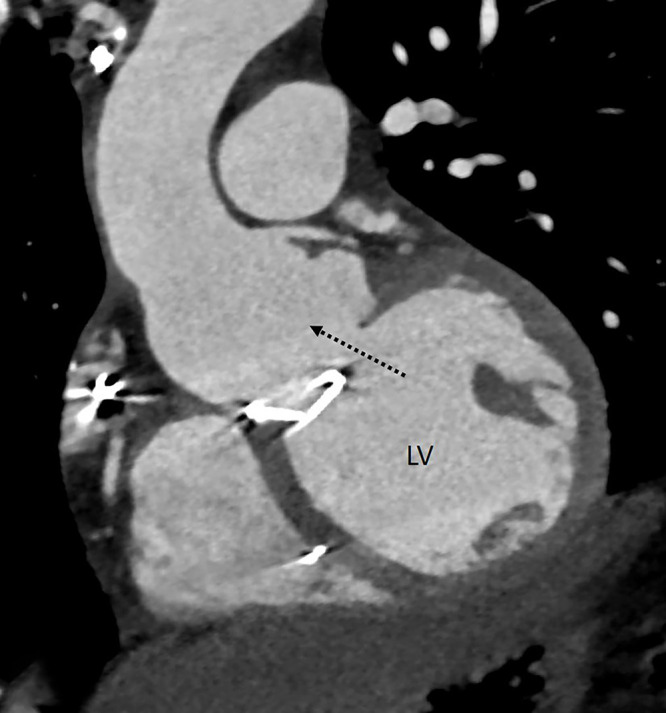
Dehiscence. Oblique coronal CT angiography image shows a gap between the annulus and mechanical prosthetic aortic valve (dashed black arrow) with communication between the aortic root and left ventricular outflow. LV = left ventricle.
Paravalvular Leak
PVL is characterized by inappropriate apposition of the PHV ring to the native tissues, leading to peri-PHV regurgitation (13). The prevalence of PVL is 2%–10% in prosthetic aortic valves and 7%–17% in prosthetic mitral valves (14). Most commonly PVL is a result of dehiscence secondary to endocarditis; other causes include incorrect valve suturing to annulus and age-related degeneration of adjacent tissue (14). PVL can also be observed without definitive evidence of dehiscence owing to altered configuration between the annulus and the prosthetic valve induced by hemodynamic changes after surgery (15). Although echocardiography is the best modality for evaluation of PVL, CTA may be performed in cases of complex leaks and cases in which the usefulness of echocardiography is limited owing to the presence of eccentric jets and acoustic artifacts (13). Imaging finding at CT includes a paravalvular contrast column connecting the proximal and distal chambers.
PVL should be evaluated on a true axial double-oblique reconstruction because a crescentic leak along the imaging plane can be missed on the coronal or sagittal view (16). Location of PVL in relation to the PHV should be communicated as per a clock-face orientation from the surgeon's perspective, wherein the surgeon would view the mitral PHV from the left atrium with the heart rotated. For example, to describe PVL in the mitral position, the 12-o'clock position is assigned to the anterior part of the mitral ring (at the level of the aortic valve) and the 9-o'clock position is assigned to the level of the left atrial appendage (13) (Fig 4). A PVL must be differentiated from a suture or pledget material, which also appears as a high attenuation region; however, its CT attenuation is higher compared with contrast material (17). Another mimic includes the beam-hardening artifact, which occurs in areas in which the prosthetic leaflets connect to the valve ring; such artifact can be minimized by reconstructing the images using a soft-tissue window adjustment or iterative reconstruction (16).
Figure 4:

Paravalvular leak. (A) Oblique coronal image depicts paravalvular leak (dashed black arrow) adjacent to a mechanical prosthetic mitral valve. (B) Multiplanar reconstructed image and (C) schematic image depict the surgeon's perspective and reveal contrast material–filled channel (dotted outline in B and blue areas in C) adjacent to the prosthetic mitral valve at the 10-o'clock and 2- to 3-o'clock position. The patient had no prior history of infective endocarditis, so paravalvular leak was likely induced by hemodynamic changes after surgery. LAA = left atrial appendage.
Thrombus
The incidence of PHV thrombosis ranges from 0.3% to 8% (2). Mechanical PHVs are more frequently affected compared with bioprosthetic PHVs, and right-sided valves are more affected than left-sided valves (4). PHV thrombosis most commonly occurs in the first postoperative year, although it can occur any time after implantation (18). Risk factors include a low-flow state, suboptimal anticoagulation, pregnancy, and incomplete endothelization in the early postoperative period (4). PHV thrombosis is the most common cause of mechanical PHV obstruction.
A thrombus can lead to absent or limited motion of PHV leaflets. Cine fluoroscopy can depict the restricted PHV motion. Echocardiography can depict thrombus as a globular mobile mass with signs of obstruction but cannot detect small and laminar cusp thrombosis (3). CTA is superior to these modalities in the characterization of thrombus and depicts the presence of large, irregular, nonenhancing soft tissue attached to the leaflets, sewing ring, or both, predominantly of the aortic side of the PHV (Fig 5, Movie 2). It also allows for both quantitative and qualitative evaluation of the restricted motion of the leaflets independent of valve orientation and position. It is extremely important to differentiate thrombus from pannus for selection of optimal treatment (Table 2). A 2015 study suggested that a cutoff greater than or equal to 145 HU has a sensitivity of 87.5% and specificity of 95.5% in discriminating pannus from thrombus (19). The same study also provided insight into the optimal treatment method and outcomes after thrombolysis for periprosthetic lesions. Thrombus with CT attenuation less than 90 HU is completely lysable, whereas complete lysis is unlikely in thrombus with attenuation between 90 and 145 HU. Masses with CT attenuation greater than or equal to 145 HU represent pannus that would benefit from surgery (19). Thus, CT can also predict response to thrombolysis. It should be borne in mind, however, that the Hounsfield unit cutoff between pannus and thrombus is based on the findings of a single study, and further studies are necessary to confirm these findings. MRI has limited spatial and temporal resolution, which makes detection of small thrombi difficult (4).
Figure 5:

Thrombus. (A) Oblique coronal image depicts irregular hypoattenuating soft tissue with a mean CT attenuation of 86 HU predominantly on the aortic side of the prosthesis. Images in the systolic (B) and diastolic (C) phase show restricted mobility of the valve leaflets with abnormal opening angles. deg = degrees, Max = maximum, Min = minimum, SD = standard deviation.
Table 2:
Difference between Prosthetic Heart Valve Thrombus and Pannus

Movie 2:
Cine loop in the oblique coronal projection shows thrombus involving the prosthetic aortic valve with reduced range of movement of both leaflets.
Hypoattenuating Leaflet Thickening
Subclinical leaflet thrombosis (SLT) has been described as a complication after transcatheter aortic valve replacement but was demonstrated subsequently in transcatheter as well as surgical bioprosthetic valves (20). The underlying mechanism of leaflet thrombosis can be explained by the Virchow triad, with the contributing factors being low flow states, leaflet injury, and prothrombotic conditions. Most patients are asymptomatic, and recent studies suggest that SLT is primarily an imaging finding (20). Echocardiography reveals no changes in mean pressure gradient. Currently, CT is considered the standard modality for diagnosing SLT. Hypoattenuating material associated with bioprosthetic valve described as hypoattenuating leaflet thickening (HALT) is the hallmark of SLT (Fig 6). The hypoattenuating lesions are seen at the periphery and base of leaflets and can lead to reduced leaflet mobility (RELM). The simultaneous occurrence of HALT and RELM is termed hypoattenuation affecting motion (HAM) (21). A clear visualization of leaflet coaptation in the diastolic phase without hypoattenuation excludes its presence (20). The natural history of this entity is not well known. Although SLT does not have immediate clinical consequences, there is concern regarding the possibility of complications such as embolic phenomenon or premature degeneration (21). Dual antiplatelet or single antiplatelet therapy appears to be less effective in the prevention and management of SLT. In a few observational studies (37, 38), oral anticoagulants were shown to have protective or therapeutic efficacy. Multiple ongoing trials will provide better data regarding the most effective drug for the management of SLT (21).
Figure 6:
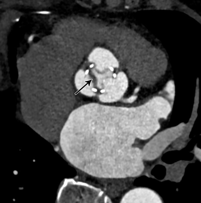
Hypoattenuating leaflet thickening several months after bioprosthetic aortic valve replacement. Oblique axial CT image demonstrates thickened and hypoattenuating leaflet (black arrow) of bioprosthetic aortic valve.
Pannus
The formation of pannus is a gradual process, with PHV obstruction occurring several months after surgery (22). Pannus is constituted of fibroblasts and microvascular channels enveloping and infiltering the prosthesis from beneath the sewing ring to the base of the leaflets, causing restricted motion. Echocardiography can detect hemodynamic effects of pannus but is suboptimal for tissue characterization. CT can help in identifying the presence and location of pannus. The soft tissue shows enhancement owing to neovascularization of fibrous tissue and may show calcification (3) (Fig 7). Pannus should be differentiated from pseudolesions that occur owing to beam-hardening artifact. These artifacts have low attenuation compared with the myocardium and are seen in select phases of the cardiac cycle (23). The extension of pannus in the subvalvular area should be quantified by measuring the geometric orifice area and encroachment ratio of PHV. The majority of the patients show coexistence of thrombus and pannus; formation of thrombus is attributed to the areas of stagnant flow generated during the course of gradual accrual of pannus (22, 23). CT is limited by lack of hemodynamic assessment; such assessment can be done using MRI, but pannus cannot be directly visualized at MRI.
Figure 7:

Pannus. (A) Four-chamber and (B) oblique coronal CT images demonstrate circumferential soft tissue (dotted black arrows in A) in a bioprosthetic mitral valve with CT attenuation of 186 HU. Max = maximum, Min = minimum, SD = standard deviation.
Infective Endocarditis and Vegetations
PHV endocarditis is often fatal, with mortality ranging between 20% and 40%, and requires prompt diagnosis and early treatment (24). The high mortality rate can be attributed to high likelihood of infection spreading to the periprosthetic tissue. While PHV endocarditis can occur at any time after implantation, it is most commonly observed in the initial 5 years (4). In a mechanical PHV the infection spreads from the sewing ring or the adjacent thrombus, whereas in bioprosthetic PHV the infection begins in the leaflet cusps (25). Transthoracic and transesophageal echocardiography are the first-line imaging modalities for patients with suspected PHV endocarditis (26). Echocardiography has high temporal resolution to accurately identify mobile vegetation and can assess hemodynamic consequences of valve damage. However, echocardiographic evaluation of mechanical prosthetic valves can be limited by artifacts owing to acoustic window. CTA can accurately assess perivalvular complications, including abscesses and aneurysms (26). CTA also plays an important role in preoperative evaluation of the retrosternal area and coronary artery anatomy (27). In one study, the incorporation of CTA in the assessment of patients with infective endocarditis changed the treatment strategy in 25% of patients; this modality can identify life-threatening complications (aneurysm and abscesses) that can be missed at echocardiography (28). The imaging findings of PHV endocarditis at CTA include vegetations, aortic wall thickening greater than 5 mm, perivalvular abscess, and pseudoaneurysm (29). At CTA, vegetations are seen as irregular, low-attenuation mobile masses adherent to the prosthetic valve leaflet or sewing ring (Fig 8). CTA has excellent sensitivity in identifying large vegetations (>10 mm in size); however, its role is limited in evaluating small vegetations (<4 mm in size) and perforations (26). Another limitation in the evaluation of PHV is the presence of streak artifacts caused by the high density of the PHV material (29). CTA also plays an important role in detecting extracardiac abnormalities, including intra-abdominal lesions (splenic, renal, and hepatic abscess or infarction), central nervous system lesions, and septic pulmonary emboli in patients with PHV endocarditis (26).
Figure 8:

Vegetation. (A) Three-chamber and (B) short-axis CT angiography images in a patient with infective endocarditis reveal low-attenuation soft tissue (black arrow) adherent to bioprosthetic aortic valve, which is suggestive of vegetation with adjacent pseudoaneurysm (asterisk in B). LA = left atrium.
Abscess.— The extension of infection to the perivalvular region is more frequently observed in PHVs compared with native valves. In initial stages, the infection spreads to the vessel wall, causing thickening with subsequent tissue destruction, leading to abscess formation. Echocardiography can depict abscess as anechoic cavity but does not provide clear anatomic delineation and extent of involvement. CT is almost 100% accurate in identifying abscess compared with surgical findings and allows the evaluation of adjacent structures (30). At CT, perivalvular abscesses are seen as fluid attenuation collection around the PHV with adjacent inflammatory soft tissue and fat stranding (29) (Fig 9). Rim enhancement can be seen on delayed images with occasional presence of gas. The abscess can spread into surrounding cardiac structures. In cases associated with aortic PHV, the spread of infection is mainly seen in mitral-aortic intervalvular fibrosis, whereas in cases associated with mitral PHV, spread occurs posteriorly or laterally (31).
Figure 9:

Abscess. (A) Oblique coronal and (B) axial CT images in a patient with infective endocarditis depict a collection (white asterisk) showing peripheral rim enhancement (white arrows) adjacent to a mechanical aortic valve. Note the contrast material–filled pseudoaneurysm (black asterisk in B) posterior to it.
Pseudoaneurysm.— The rupture of a periprosthetic abscess can lead to formation of a pseudoaneurysm. Pseudoaneurysms are commonly seen in the aorta; risk factors for this are hypertension, connective tissue disorders, and presence of calcification (32). Echocardiography depicts pseudoaneurysm as an anechoic space surrounding the PHV, with color flow within. However, such an anechoic space can also be seen in patients after undergoing the Bentall procedure secondary to wrapping of the aorta around the graft (4). CTA is almost 100% accurate in diagnosing pseudoaneurysm (33,34). At CTA, pseudoaneurysm appears as a contrast material–filled saccular or fusiform outpouching. While pseudoaneurysms can be of variable sizes and shapes, they usually have a narrow neck and may show expansion and reduction in size during systole and diastole, respectively (Fig 10, Movies 3 and 4). CTA can also assess associated complications such as coronary compression, thromboembolism, and rupture (32). It is necessary to differentiate pseudoaneurysm from abscess in the periprosthetic region. An abscess does not communicate with an adjacent cardiac chamber or aorta and does not show contrast opacification of the cavity; however, when a periprosthetic abscess drains into the cardiac chamber or aorta, thereby forming a pseudoaneurysm, contrast opacification of the outpouching is observed.
Figure 10:

Pseudoaneurysm. (A) Four-chamber and (B) oblique coronal CT angiography images depict contrast material–filled saccular outpouching (black asterisk) adjacent to the prosthetic mitral valve.
Movie 3:
Cine loop in the four-chamber view shows contrast material–filled saccular outpouching adjacent to bioprosthetic mitral valve.
Movie 4:
Cine loop in the oblique coronal projection shows contrast material–filled saccular outpouching adjacent to bioprosthetic mitral valve.
Fistula.— Formation of fistula is a rare complication and occurs when an abscess or pseudoaneurysm ruptures into adjacent cardiac chambers. Fistula most commonly occurs between the right coronary sinus and the right ventricle, with the next most common locations between the noncoronary sinus and right ventricle and between the left coronary sinus and left atrium (35). The presence of an abscess is observed in three-quarters of abnormal connections (35). An abnormal communication between the left ventricle and right atrium resulting in a left-to-right shunt is known as Gerbode defect (36). Echocardiography can delineate these fistulas owing to the high turbulence across them secondary to the pressure gradient. CTA demonstrates the morphology and extent of fistulas better than echocardiography but does not depict shunt quantification well; shunt quantification can be depicted at MRI.
Conclusion
CTA provides high-resolution, detailed anatomic and structural information in numerous, potentially life-threatening PHV complications (Table 3) and thus complements the other imaging modalities. It is imperative that radiologists, cardiologists, and cardiac surgeons are aware of the imaging spectrum of valvular and perivalvular complications at CTA to enable accurate diagnosis of the cause of PHV dysfunction and guide appropriate management.
Table 3:
Spectrum of Imaging Findings at CT Angiography in Various Complications of Prosthetic Heart Valves

M.V. and N.N.P. contributed equally to this work.
Authors declared no funding for this work.
Disclosures of Conflicts of Interest: M.V. disclosed no relevant relationships. N.N.P. disclosed no relevant relationships. S.K. disclosed no relevant relationships. S.R. disclosed no relevant relationships.
Abbreviations:
- CTA
- CT angiography
- ECG
- electrocardiography
- HALT
- hypoattenuating leaflet thickening
- HAM
- hypoattenuation affecting motion
- PVL
- paravalvular leak
- PHV
- prosthetic heart valve
- RELM
- reduced leaflet mobility
- SLT
- subclinical leaflet thrombosis
References
- 1. Habets J , Mali WPTM , Budde RPJ . Multidetector CT angiography in evaluation of prosthetic heart valve dysfunction . RadioGraphics 2012. ; 32 ( 7 ): 1893 – 1905 . [DOI] [PubMed] [Google Scholar]
- 2. Lancellotti P , Pibarot P , Chambers J , et al . Recommendations for the imaging assessment of prosthetic heart valves: a report from the European Association of Cardiovascular Imaging endorsed by the Chinese Society of Echocardiography, the Inter-American Society of Echocardiography, and the Brazilian Department of Cardiovascular Imaging . Eur Heart J Cardiovasc Imaging 2016. ; 17 ( 6 ): 589 – 590 . [DOI] [PubMed] [Google Scholar]
- 3. Andrews JPM , Cartlidge TR , Dweck MR , Moss AJ . Cardiac CT in prosthetic aortic valve complications . Br J Radiol 2019. ; 92 ( 1093 ): 20180237 . [DOI] [PMC free article] [PubMed] [Google Scholar]
- 4. Rajiah P , Moore A , Saboo S , et al . Multimodality Imaging of Complications of Cardiac Valve Surgeries . RadioGraphics 2019. ; 39 ( 4 ): 932 – 956 . [DOI] [PubMed] [Google Scholar]
- 5. Faure ME , Swart LE , Dijkshoorn ML , et al . Advanced CT acquisition protocol with a third-generation dual-source CT scanner and iterative reconstruction technique for comprehensive prosthetic heart valve assessment . Eur Radiol 2018. ; 28 ( 5 ): 2159 – 2168 . [DOI] [PMC free article] [PubMed] [Google Scholar]
- 6. Priya S , Nagpal P , Vidholia A , Sachdev IS , Ashwath R . Evaluation of Transcatheter Pulmonary Valve Endocarditis by Dual-Energy Computed Tomography . Cureus 2020. ; 12 ( 6 ): e8851 . [DOI] [PMC free article] [PubMed] [Google Scholar]
- 7. Habets J , Symersky P , Leiner T , de Mol BAJM , Mali WP , Budde RPJ . Artifact reduction strategies for prosthetic heart valve CT imaging . Int J Cardiovasc Imaging 2012. ; 28 ( 8 ): 2099 – 2108 . [DOI] [PMC free article] [PubMed] [Google Scholar]
- 8. Moss AJ , Dweck MR , Dreisbach JG , et al . Complementary role of cardiac CT in the assessment of aortic valve replacement dysfunction . Open Heart 2016. ; 3 ( 2 ): e000494 . [DOI] [PMC free article] [PubMed] [Google Scholar]
- 9. Saleeb SF , Newburger JW , Geva T , et al . Accelerated degeneration of a bovine pericardial bioprosthetic aortic valve in children and young adults . Circulation 2014. ; 130 ( 1 ): 51 – 60 . [DOI] [PubMed] [Google Scholar]
- 10. Jilaihawi H , Makkar RR , Kashif M , et al . A revised methodology for aortic-valvar complex calcium quantification for transcatheter aortic valve implantation . Eur Heart J Cardiovasc Imaging 2014. ; 15 ( 12 ): 1324 – 1332 . [DOI] [PubMed] [Google Scholar]
- 11. Blot WJ , Ibrahim MA , Ivey TD , et al . Twenty-five-year experience with the Björk-Shiley convexoconcave heart valve: a continuing clinical concern . Circulation 2005. ; 111 ( 21 ): 2850 – 2857 . [DOI] [PubMed] [Google Scholar]
- 12. Rizzoli G , Russo R , Valente S , et al . Dehiscence of aortic valve prostheses: analysis of a ten-year experience . Int J Cardiol 1984. ; 6 ( 2 ): 207 – 221 . [DOI] [PubMed] [Google Scholar]
- 13. Lázaro C , Hinojar R , Zamorano JL . Cardiac imaging in prosthetic paravalvular leaks . Cardiovasc Diagn Ther 2014. ; 4 ( 4 ): 307 – 313 . [DOI] [PMC free article] [PubMed] [Google Scholar]
- 14. Ionescu A , Fraser AG , Butchart EG . Prevalence and clinical significance of incidental paraprosthetic valvar regurgitation: a prospective study using transoesophageal echocardiography . Heart 2003. ; 89 ( 11 ): 1316 – 1321 . [DOI] [PMC free article] [PubMed] [Google Scholar]
- 15. Englberger L , Schaff HV , Jamieson WRE , et al . Importance of implant technique on risk of major paravalvular leak (PVL) after St. Jude mechanical heart valve replacement: a report from the Artificial Valve Endocarditis Reduction Trial (AVERT) . Eur J Cardiothorac Surg 2005. ; 28 ( 6 ): 838 – 843 . [DOI] [PubMed] [Google Scholar]
- 16. O'Neill AC , Martos R , Murtagh G , et al . Practical tips and tricks for assessing prosthetic valves and detecting paravalvular regurgitation using cardiac CT . J Cardiovasc Comput Tomogr 2014. ; 8 ( 4 ): 323 – 327 . [DOI] [PubMed] [Google Scholar]
- 17. Habets J , Meijer TS , Meijer RCA , Mali WPTM , Vonken EJPA , Budde RPJ . CT attenuation measurements are valuable to discriminate pledgets used in prosthetic heart valve implantation from paravalvular leakage . Br J Radiol 2012. ; 85 ( 1017 ): e616 – e621 . [DOI] [PMC free article] [PubMed] [Google Scholar]
- 18. Deviri E , Sareli P , Wisenbaugh T , Cronje SL . Obstruction of mechanical heart valve prostheses: clinical aspects and surgical management . J Am Coll Cardiol 1991. ; 17 ( 3 ): 646 – 650 . [DOI] [PubMed] [Google Scholar]
- 19. Gündüz S , Özkan M , Kalçik M , et al . Sixty-Four-Section Cardiac Computed Tomography in Mechanical Prosthetic Heart Valve Dysfunction: Thrombus or Pannus . Circ Cardiovasc Imaging 2015. ; 8 ( 12 ): e003246 . [DOI] [PubMed] [Google Scholar]
- 20. Jilaihawi H , Asch FM , Manasse E , et al . Systematic CT Methodology for the Evaluation of Subclinical Leaflet Thrombosis . JACC Cardiovasc Imaging 2017. ; 10 ( 4 ): 461 – 470 [Published correction appears in JACC Cardiovasc Imaging 2017;10(6):718.] . [DOI] [PubMed] [Google Scholar]
- 21. Oliveira DC , Okutucu S , Russo G , Martins ECC . The Issue of Subclinical Leaflet Thrombosis After Transcatheter Aortic Valve Implantation . Cardiol Res 2020. ; 11 ( 5 ): 269 – 273 . [DOI] [PMC free article] [PubMed] [Google Scholar]
- 22. Vitale N , Renzulli A , Agozzino L , et al . Obstruction of mechanical mitral prostheses: analysis of pathologic findings . Ann Thorac Surg 1997. ; 63 ( 4 ): 1101 – 1106 . [DOI] [PubMed] [Google Scholar]
- 23. Aladmawi MA , Pragliola C , Vriz O , Galzerano D . Use of multidetector-row computed tomography scan to detect pannus formation in prosthetic mechanical aortic valves . J Thorac Dis 2017. ; 9 ( Suppl 4 ): S343 – S348 . [DOI] [PMC free article] [PubMed] [Google Scholar]
- 24. Wang A , Athan E , Pappas PA , et al . Contemporary clinical profile and outcome of prosthetic valve endocarditis . JAMA 2007. ; 297 ( 12 ): 1354 – 1361 . [DOI] [PubMed] [Google Scholar]
- 25. Piper C , Körfer R , Horstkotte D . Prosthetic valve endocarditis . Heart 2001. ; 85 ( 5 ): 590 – 593 . [DOI] [PMC free article] [PubMed] [Google Scholar]
- 26. Erba PA , Pizzi MN , Roque A , et al . Multimodality Imaging in Infective Endocarditis: An Imaging Team Within the Endocarditis Team . Circulation 2019. ; 140 ( 21 ): 1753 – 1765 . [DOI] [PubMed] [Google Scholar]
- 27. Chaosuwannakit N , Makarawate P . Value of cardiac computed tomography angiography in pre-operative assessment of infective endocarditis . J Cardiothorac Surg 2019. ; 14 ( 1 ): 56 . [DOI] [PMC free article] [PubMed] [Google Scholar]
- 28. Habets J , Tanis W , van Herwerden LA , et al . Cardiac computed tomography angiography results in diagnostic and therapeutic change in prosthetic heart valve endocarditis . Int J Cardiovasc Imaging 2014. ; 30 ( 2 ): 377 – 387 . [DOI] [PubMed] [Google Scholar]
- 29. Murphy DJ , Keraliya AR , Agrawal MD , Aghayev A , Steigner ML . Cross-sectional imaging of aortic infections . Insights Imaging 2016. ; 7 ( 6 ): 801 – 818 . [DOI] [PMC free article] [PubMed] [Google Scholar]
- 30. Feuchtner GM , Stolzmann P , Dichtl W , et al . Multislice computed tomography in infective endocarditis: comparison with transesophageal echocardiography and intraoperative findings . J Am Coll Cardiol 2009. ; 53 ( 5 ): 436 – 444 . [DOI] [PubMed] [Google Scholar]
- 31. Habib G , Hoen B , Tornos P , et al . Guidelines on the prevention, diagnosis, and treatment of infective endocarditis (new version 2009): the Task Force on the Prevention, Diagnosis, and Treatment of Infective Endocarditis of the European Society of Cardiology (ESC). Endorsed by the European Society of Clinical Microbiology and Infectious Diseases (ESCMID) and the International Society of Chemotherapy (ISC) for Infection and Cancer . Eur Heart J 2009. ; 30 ( 19 ): 2369 – 2413 . [DOI] [PubMed] [Google Scholar]
- 32. Parihar B , Choudhary LSD , Madhu AP , Alpha MK , Thankachen R , Shukla V . Pseudoaneurysm of ascending aorta after aortic valve replacement . Ann Thorac Surg 2005. ; 79 ( 2 ): 705 – 707 . [DOI] [PubMed] [Google Scholar]
- 33. Gahide G , Bommart S , Demaria R , et al . Preoperative evaluation in aortic endocarditis: findings on cardiac CT . AJR Am J Roentgenol 2010. ; 194 ( 3 ): 574 – 578 . [DOI] [PubMed] [Google Scholar]
- 34. Fagman E , Perrotta S , Bech-Hanssen O , et al . ECG-gated computed tomography: a new role for patients with suspected aortic prosthetic valve endocarditis . Eur Radiol 2012. ; 22 ( 11 ): 2407 – 2414 . [DOI] [PubMed] [Google Scholar]
- 35. Anguera I , Miro JM , Vilacosta I , et al . Aorto-cavitary fistulous tract formation in infective endocarditis: clinical and echocardiographic features of 76 cases and risk factors for mortality . Eur Heart J 2005. ; 26 ( 3 ): 288 – 297 . [DOI] [PubMed] [Google Scholar]
- 36. Yuan SM . A Systematic Review of Acquired Left Ventricle to Right Atrium Shunts (Gerbode Defects) . Hellenic J Cardiol 2015. ; 56 ( 5 ): 357 – 372 . [PubMed] [Google Scholar]
- 37. Ruile P , Jander N , Blanke P , et al . Course of early subclinical leaflet thrombosis after transcatheter aortic valve implantation with or without oral anticoagulation . Clin Res Cardiol 2017. ; 106 ( 2 ): 85 – 95 . [DOI] [PubMed] [Google Scholar]
- 38. Hansson NC , Grove EL , Andersen HR , et al . Transcatheter aortic valve thrombosis: incidence, predisposing factors, and clinical implications . J Am Coll Cardiol 2016. ; 68 ( 19 ): 2059 – 2069 . [DOI] [PubMed] [Google Scholar]