-
A
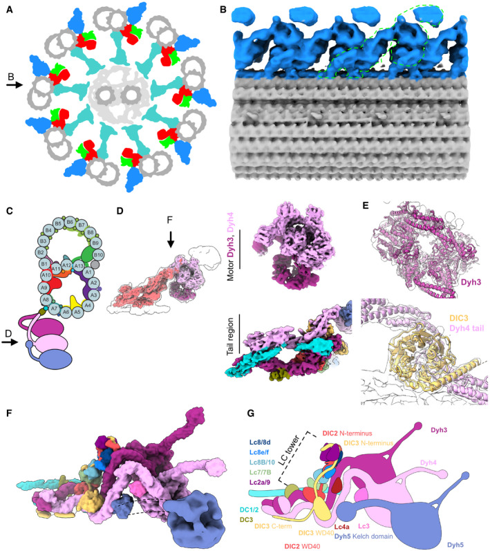
Schematic diagram of axoneme structure of cilia viewed from the base of the cilia. Doublet microtubule: gray; outer dynein arm: blue; inner dynein arm: red; dynein regulatory complex: green; radial spokes: cyan. Black arrow indicates the view in (B).
-
B
The 24‐nm structure of the doublet microtubule from K40R mutant filtered to 18 Å showing the row of the ODA. The green outline indicates the single ODA complex.
-
C
A schematic cartoon of the doublet microtubule and the ODA complex. Arrow indicates the view in (D).
-
D
The focused refined maps of the tail and the heads of the ODA are shown within the map of the entire ODA complex (left). The focused refined maps of Dyh3 and Dyh4 heads and the tail (right).
-
E
Fitting of models into maps (Dyh3, top; DIC3 and Dyh4 tail, bottom). The α‐helix part of the DIC3 was more structured in our map compared with that of the Shulin–ODA complex.
-
F, G
The surface render of the model (F) and the schematic cartoon (G) of the ODA with the docking complex. The Dyh5 is too flexible to resolve well by cryo‐EM. The Dyh5 head is only shown as the 18‐Å resolution surface render, and the Dyh5 tail is drawn as dotted lines. All the components (ICs, LCs, and DCs) are colored and indicated and will be used consistently in all the figures. C‐terminal side of the DIC3 has more structured region along the Dyh4 HC tail on the doublet.

