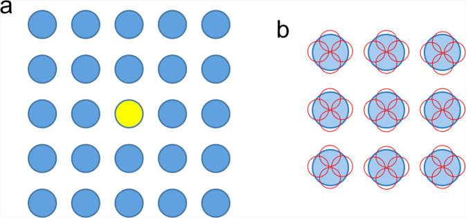
Fig. 1. Schematic diagram of data taking for SPA through image shifts.
a Stage shift is only used to locate the central hole in yellow, and image shifts are applied for data taking from other 24 holes in this example. b Multiple images stacks, 4 in this example, are recorded from different areas shown in small red circles in one hole. Pre-check of the surrounding holes is unsuitable for fast collection of images stacks from each hole.

