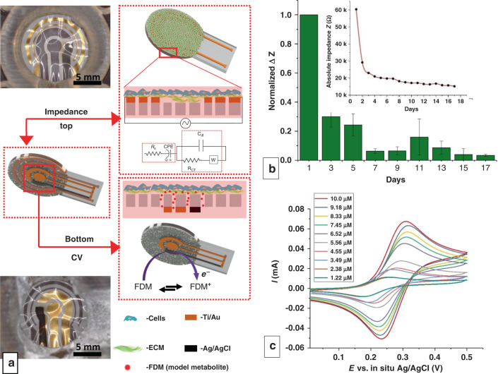
Fig. 6. Multimodal sensor-integrated transwell system.
a Optical images and schematic illustrations of the multimodal sensors displaying both impedimetric (top view) and CV (bottom view) sensors. Electrodes in view are lustrous Au and black Ag/AgCl, while electrodes on the opposite side of the translucent membrane are gray due to the Ti adhesion layer. Membranes appear wrinkled due to thermal expansion during PDMS curing. b Normalized change in impedance values measured at 10 Hz over the course of 17 days. (n = 3, measurements from 3 separate devices). The inset shows the absolute change in impedance from one of the devices tested. c CV following the addition of 10 aliquots of 100 µL of 10 mM FDM on the apical side of the gut triculture. The legend displays the final experimental concentration

