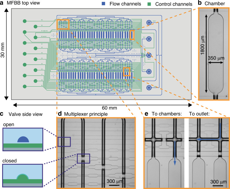
Fig. 1. Design and operation of the mLSI MFBB.
a Schematic design of the mLSI MFBB. The channels in the flow layer are shown in blue, while the channels in the control layer are shown in green. b Brightfield micrograph of a chamber. c Schematic side view of a valve in normally open “push-up” configuration. d Brightfield micrograph illustrating the multiplexing principle for the first four chambers. e The brightfield micrograph on the left shows the bypass channel blocked by valves, whereby the flow is directed into the chambers. The right micrograph shows the chambers blocked by valves, and the bypass channel opened. As a result, the flow is directed to the outlet, purging the channels without mixing with the chamber content

