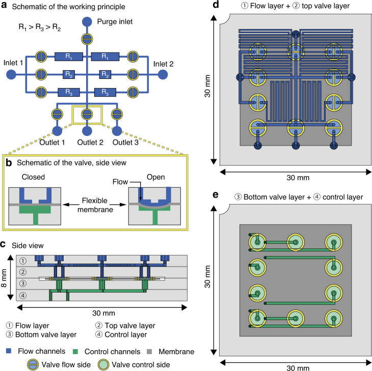
Fig. 2. Design and operation of the dosing MFBB.
a Schematic diagram of the MFBB working principle. b Schematic side view of the integrated valves. c Realistic side view of the MFBB showing all four layers. d Realistic top view of the flow layer, containing the in- and outlets, the hydraulic resistors (layer ①) and the top part of the valves (layer ②). e Realistic top view of the control layer, containing the control channels (layer ③) and the bottom part of the valves (layer ④)

