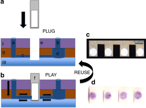
Fig. 2. Working principle of the hybrid PnP microfluidic device.

The figure shows the cross-sectional view of the hybrid PnP microfluidic device without the paper substrate (a) in the slot and with the paper substrate in the slot (b). The top layer consists of inlet microwells (a) and reservoir microwells (b). The middle layer consists of channels (c) and reservoirs (d). Slots (e) pass through the top, middle and half of the bottom layers where the paper substrate (f) can be inserted vertically. Scanned image of the SU-8-treated paper substrate before the immunoassay (c) and after the immunoassay (d).
