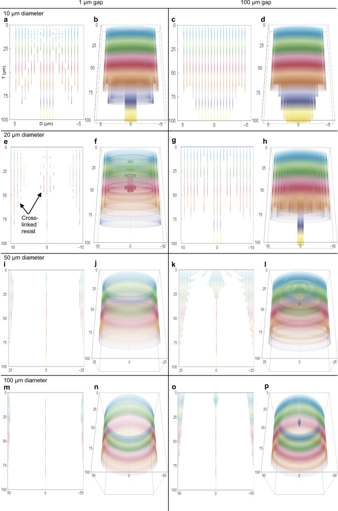
Fig. 3. Latent image simulations of varying photomask occulter diameters and air gaps.
The ordinate is the top downwards photoresist thickness, T, (µm), and the abscissa is the feature diameter, D, (µm). The unobstructed aerial ED = 1700 mJ/cm2, diffraction λ=405 nm and the simulation resolution is 0.5 µm for (a–d) and 1 µm for (e–p). The figure color scales with photoresist thickness to differentiate between height levels, where colored data points represent sites of cross-linked photoresist. Rows 1–4 correspond to 10, 20, 50, and 100 µm diameter circular occulters, respectively. Columns 1–2 and 3–4 correspond to air gaps of 1 and 100 µm. a 2D x-z photoresist cross-section with D=10 µm and g=1 µm. Light intensity calculation time (t) = 2 s. b 3D wrap-around view of (a) with a z-axis of rotation at x=0 and y=0. c 2D cross-section with D=10 µm, g=100 µm and t = 1 s. d 3D wrap-around view of (c). e 2D cross-section with D=20 µm, g=1 µm and t = 5 s. f 3D wrap-around view of (e). g 2D cross-section with D=20 µm, g=100 µm and t = 1 s. h 3D wrap-around view of (g). i 2D cross-section with D=50 µm, g=1 µm and t = 37 s. j 3D wrap-around view of (i). k 2D cross-section with D=50 µm, g=100 µm and t = 15 s. l 3D wrap-around view of (k). m 2D cross-section with D=100 µm, g=1 µm and t = 1 m 41 s. n 3D wrap-around view (m). o 2D cross-section with D=100 µm, g=100 µm and t = 1 m 1 s. p 3D wrap-around view of (o)

