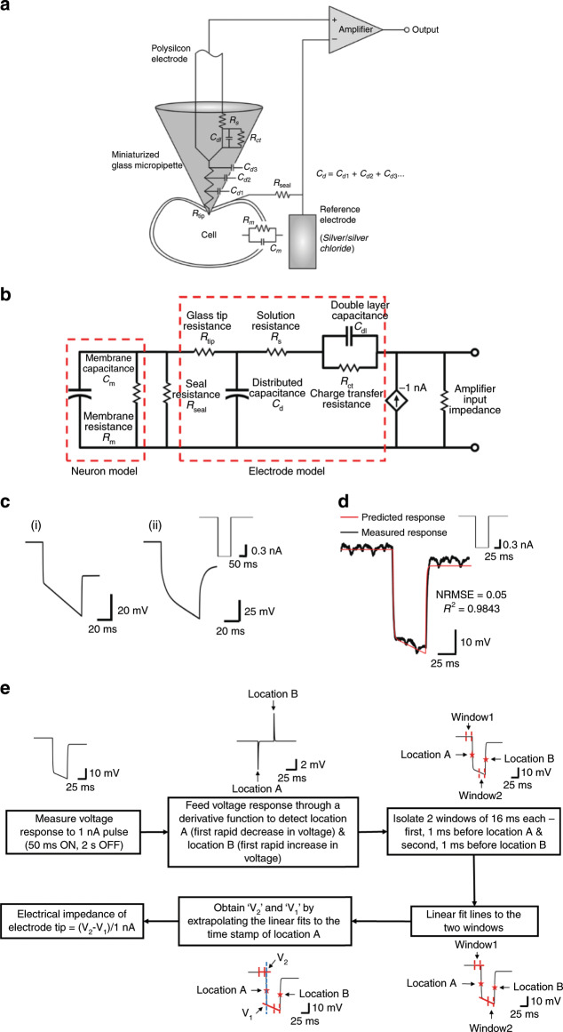
Fig. 3. Modeling the electrical impedance of glass–polysilicon (GP) microelectrode.
a Schematic representing the elements of the microelectrode–neuron interface. b Equivalent electrical circuit of the electrode–neuron interface. Rseal represents the degree of coupling between the electrode and neuronal membrane. c Expected (ideal) voltage responses of this electrode to application of a 1-nA current pulse (shown in inset) for 2 conditions: (i) Seal resistance (Rseal) of 0.1 MΩ (simulating a condition of electrode away from neuron), (ii) Seal resistance (Rseal) of 1 GΩ (simulating a condition of electrode inside neuron). d Measured voltage response of a GP microelectrode to the application of a 1-nA pulse matches well with the response predicted by the model for Rseal = 0.1 MΩ. e Sequence of steps involved in quantitative measurement of electrical impedance of the tip of the glass–polysilicon microelectrode.

