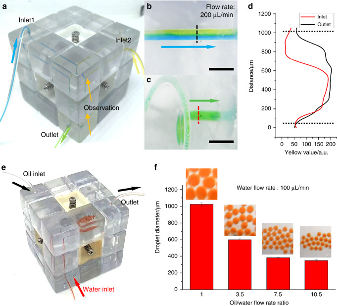
Fig. 6. Photographs of functional microfluidics systems configured using the proposed cube.
a A microfluidic mixer consisting of the inlet/outlet, channel, junction, and spiral channel blocks. Enlarged images of dye solution flow before entering (b) and leaving (c) the spiral channel block (scale bars: 2 mm). d Yellow value distribution in the microfluidic channel with changing distance along the dashed lines. e A water-in-oil droplet generator consisting of the inlet/outlet, channel, junction, and planar chamber blocks. f Droplet size variance when changing the water/oil flow rate ratio

