Abstract
Novel severe acute respiratory syndrome coronavirus 2 (COVID-19) has become a pandemic of epic proportions, and global response to prepare health systems worldwide is of utmost importance. 2-dimensional (2D) lung ultrasound (LUS) has emerged as a rapid, noninvasive imaging tool for diagnosing COVID-19 infected patients. Concerns surrounding LUS include the disparity of infected patients and healthcare providers, and importantly, the requirement for substantial physical contact between the patient and operator, increasing the risk of transmission. New variants of COVID-19 will continue to emerge; therefore, mitigation of the virus's spread is of paramount importance. A tele-operative robotic ultrasound platform capable of performing LUS in COVID-19 infected patients may be of significant benefit, especially in low- and middle-income countries. The authors address the issues mentioned above surrounding the use of LUS in COVID-19 infected patients and the potential for extension of this technology in a resource-limited environment. Additionally, first-time application, feasibility, and safety were validated in healthy subjects. Preliminary results demonstrate that our platform allows for the successful acquisition and application of robotic LUS in humans.
Keywords: Lung ultrasound, robotic ultrasound, teleoperation
I. Introduction
Novel severe acute respiratory syndrome coronavirus 2 (COVID-19) is now a pandemic of epic proportions, affecting tens of millions of people worldwide [1]. Respiratory symptoms are the primary manifestation of COVID-19, ranging from mild illness to severe, acute, and fulminant respiratory distress and failure. This various degree of severity necessitates rapid diagnosis to provide proper triage. Diagnostic testing, including plain-film radiography (X-ray) and chest computed tomography (CT), are considered the gold standard of imaging in the detection of lung-related disease [2], [3]. However, in resource-limited areas and low- and middle-income countries, these imaging modalities are cost-prohibitive and not available at most healthcare facilities [4]. 2-dimensional (2D) lung ultrasound (LUS) has emerged as a rapid, noninvasive imaging tool for diagnosing lung disease. Its application is now widely adopted for imaging COVID-19 patients, and clinical guidelines have been recently established [5]–[7]. In addition to safety, portability, and absence of radiation, ultrasound (US) is low cost [3], [8], [9] when compared to X-ray and CT. Furthermore, a recent study demonstrated the use of LUS in patients with suspected lung disease was superior over X-ray in those who were diagnosed with pneumonia by CT [10]. In resource-limited areas, the accessibility of testing is further complicated by the small number of emergency physicians and sonographers capable of performing LUS. Additionally, the LUS exam requires considerable physical contact between the operator and patient, increasing infection risk.
A. Related Works
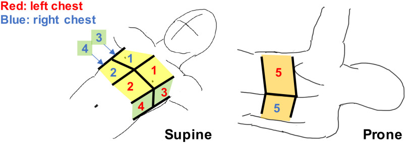
A comprehensive LUS exam requires a large area of the thorax to be scanned, and several standardized approaches have been developed for point-of-care US (POCUS). Most recently, the bedside LUS in emergency (BLUE) modified protocol [8] POCUS examination has been widely adopted for immediate diagnosis of acute respiratory failure. This protocol includes US imaging of the lungs from ten standardized spots on the anterior, lateral, and posterior chest wall, as shown in Fig. 1. Acquiring diagnostic US images at each spot requires the operator to apply a constant force to the thorax with the probe's trajectory perpendicular to the body surface.
Fig. 1.
Standardized 10 scan spots in the modified BLUE protocol. (anterior region: #1 and #2, lateral region: #3 and #4, posterior region: #5). Note that this illustration is cited as originally from [24].
We believe that robot-assisted US can play a critical role in addressing the aforementioned issues and potential limitations because the robotic assistance enables tele-operative control of the US probe, making the procedure repeatable, and decreasing the interaction and contact between the user and patient [11], [12]. To perform LUS under the BLUE protocol with the robot-assisted US, excessive contact force avoidance during the scan is necessary. According to previous studies, the sufficient contact force between the US probe and body should be less than approximately 20 N [13]–[18]. Also, the BLUE protocol requires imaging across the entire thorax. For a robot arm with serial robotic manipulators to reach both sides of the chest while avoiding collisions between the robotic joints and the patient's body, an arm's reach of at least 1200 mm is required (see Section II-B). A recent study reported the successful cardiopulmonary assessment of patients with COVID-19 using a robot-assisted remote US system [13]. In this study, the robot US system comprised the serial robotic manipulator, including six-degrees-of-freedom, coupled with an imaging system that included a convex array probe. However, it was noted that the system could not reach some scan regions on the thorax due to the robot configuration restriction, presenting a significant limitation. A high-end serial robotic manipulator could meet these requirements, permitting access to all thorax areas.
B. Design Choice
In order to conform to the scan reachability, patient safety, along with a cost-effective configuration, a design configuration combing a gantry stage with a passive-actuated end-effector is required. The gantry stage (e.g., Cartesian or linear robot) may be the only positioning configuration available as safe and reachable to all scan regions compared to other conventional configurations such as the serial robotic manipulator. As mentioned above, the required range of the reaching scan area is extensive. If the serial robotic manipulator is utilized, the required arm length is approximately more than 1200 mm based on the reference of the body size (see section II-B), and then there is a risk of the collision between the robot joint and the patient body. The gantry stage is easy to be assembled depending on the required workspace and then can provide the scan reachability with minimal risk of the joint collision issue because of its simple kinematic configuration. Also, since the gantry stage distributes loads evenly across a rigid frame, it can position large payloads and be equipped with various end-effectors. In the serial robotic manipulator, the payload capacity is limited compared to the gantry stage since loads of both the end-effector and the robot arm itself are applied directly to the motors embedded in each joint. The gantry stage is also preferable for performing an active-passive hybrid control with a customized end-effector to ensure robust patient safety, as described below. In addition, since the gantry stage's mechanism is simple, the manufacturing cost is low compared to the serial robotic manipulator. Also, to ensure patient safety, we chose the design of active control systems employed together with passive control elements in a hybrid system to control the ultrasound probe's position instead of fully active control systems. For eliminating patient discomfort and pain during the procedure, the avoidance of the excessive contact force during the scan needs to be taken into account with the robot design. If the fully active control systems are used, scanning while maintaining the contact force within a certain range requires highly accurate sensors, robust control algorithms, and computational performance that can only be satisfied by high-end robot arms. By incorporating the passive element, which is composed of only mechanical components and a sensor-free configuration into the active control system, the safety profile can be more robust as there is less reliance on the sensor and control performances. Also, the manufacturing cost may be reduced because of its sensor-free configuration.
C. Contribution
The study's goal is twofold: 1) Develop a tele-operative robotic LUS platform for COVID-19 diagnosis, minimizing the risk of transmission between the operator and patient; 2) Provide an affordable LUS platform for a resource-limited environment that of low- and middle-income countries. As previously mentioned, only one study reported applying the tele-operative robot US system to the LUS to diagnose the COVID-19 patients [13]. The study's limitation suggests that the system configuration with the serial robotic manipulator is not fully optimized for operational safety and scanning completeness for a comprehensive LUS exam. Therefore, to the best of our knowledge, this is the first dedicated robot designed for LUS. This manuscript reports an innovative approach to satisfying high usability with optimized kinematics. We believe this is a first-of-its-kind prototype of a robotic LUS scan platform based on previous concepts with a demonstration in its application in a human subject study.
II. Materials and Methods
A. System Overview
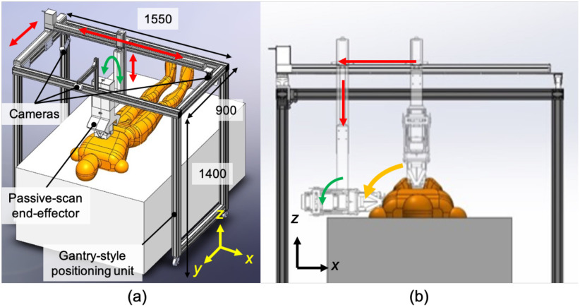
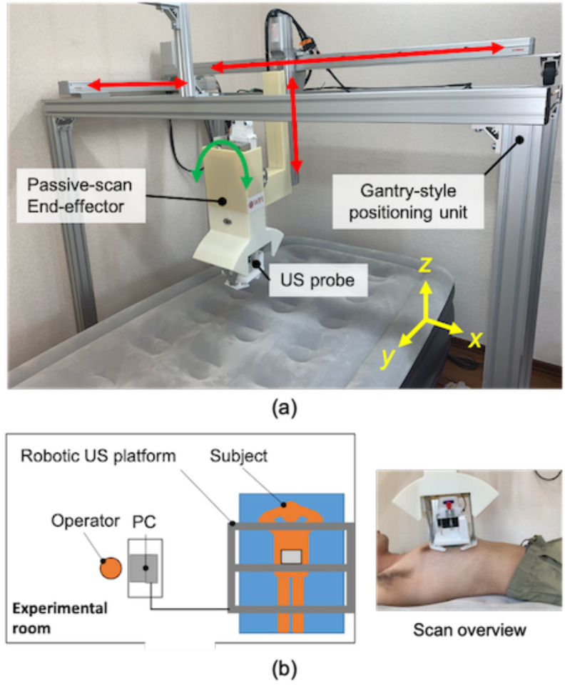
Fig. 2(a) provides an overview of the proposed robotic LUS scan platform. The platform is comprised of a gantry-style positioning unit and a passive-actuated end-effector. The positioning unit has an optimized number of joints and links to perform LUS based on the modified BLUE protocol clinical guidelines [8]. Compared with a multi-link robotic arm, the proposed gantry-style kinematics provides the reachability and maneuverability to scan both hemithoraces with minimal joint collision risk to the patient's body, as seen in Fig. 2(b). The gantry-style system is structurally simple and less costly to fabricate than a commercially available robotic arm. The end-effector equips an electronics-free, spring-based safety mechanism that maintains a constant contact force, along with normal orientation to the surface of the skin. The US probe's position and trajectory correspond to the chest surface during the scanning procedure without any sophisticated control or computation. The electronics-free passive mechanical configuration can prevent the probe from applying excessive force and ensure patient safety.
Fig. 2.
(a) Overview of the robotic LUS scan platform comprises a gantry-style positioning unit and passive-actuated end-effector (units: mm). (b) Scan on the side of chest by combining x- and z-axis translations and orientation of the end-effector.
The robotic platform has eight axes: four axes at the gantry-style positioning unit and four axes at the passive-actuated end-effector. With the robotic platform's configuration, we implemented an active-passive hybrid control to couple translation and orientation motions for a simple and intuitive manipulation interface. The manipulation of the US probe is performed via a joy-stick operation. There are three cameras with one positioned on the top and two on the sides, providing visual feedback allowing for tele-operative manipulation of the US probe based on the camera's visual information. Thus, the operator is not required to be present with the patient during the US procedure and the operator can communicate with the patient via a two-way microphone in real-time.
B. Gantry-Style Positioning Unit Design
The gantry-style positioning unit must satisfy both reachability and maneuverability to scan the whole chest with minimal collision risk to the patient body. The proposed positioning unit is comprised of three axes for translation and one axis for orientation. Referencing a human-body database created by the National Institute of Advanced Industrial Science and Technology [19], the representative chest lengths are as follows: depth 315.5 ± 16.5 mm; width 311.4 ± 17.1 mm; height 209.7 ± 19.9 mm; the required scan range can be defined approximately as an elliptical column relative to those lengths. When scanning the lateral chest regions while maintaining the probe position perpendicularly to the surface, the end-effector's orientation angle needs to be rotated to correspond to the translation motion, as shown in Fig. 2(b). The linear actuators for three translational axes and the stepper motor for orientation are selected based on the required scan range and end-effector size (See Section II-C), as shown in Table I. The workspace of the proposed configuration is shown in Fig. 3, which allows the US probe reach to be sufficient to scan the entire chest.
TABLE I. Specification of Actuators.
| Axis | Motion range | Product |
|---|---|---|
| x (transverse) | 1000 mm | BD07, Yamaha motor, Japan |
| y (longitudinal) | 500 mm | SG07, Yamaha motor, Japan |
| z (depth) | 350 mm | SG07, Yamaha motor, Japan |
| End-effector rotation | - | PKP564N28A, Oriental motor, Japan |
| Probe rotation | - | PKP214D06A, Oriental motor, Japan |
Fig. 3.
(a,b) Workspace of the gantry-style positioning unit. Solid red line includes the mean of chest region size; dotted red line includes the standard deviation of chest region size and frame oblique lines demonstrates the reachable area of the US probe.
C. Passive-Actuated End-Effector Design
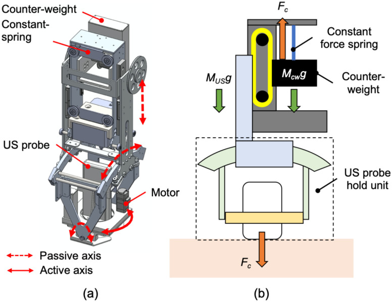
The end-effector stabilizes the US probe while applying an absolute force to the body surface. An optimal tissue-probe contact force is required when obtaining a US image [13]–[18]. A previous work focused on robotic fetal ultrasonography [14], which proposed a passive mechanism to maintain the contact force via a constant force spring and validated its feasibility through clinical studies. The advantage of the mechanical-based approach is to minimize the risk of electrical and computational failures (e.g., sensor failure and control error) and to absorb uncertain body motions and individual differences in body habitus. This concept was applied to this LUS application. An overview of the proposed end-effector is shown in Fig. 4(a). The key features of the proposed end-effector are: 1) to generate a constant force not dependent on body size via a constant force spring; 2) to maintain the probe posture perpendicular to the body surface with two passive rotational axes, and; 3) to rotate the probe angle for selecting the diagnostic view. The configuration for maintaining the contact force within a certain range is shown in Fig. 4(b). The force applied on the patient (F) is formulated as:
 |
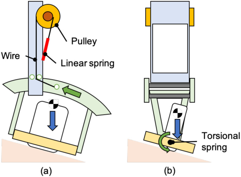
where FC is the force generated by the constant force spring. MCW and MUS are weights of the counterweight and US probe holding units, respectively. The system can maintain the force applied on the patient F to be the same as the force generated by the constant force spring when MCW = MUS. In the proposed system, we will initially use a constant force spring of 0.8 kgf, generating sufficient contact force while avoiding subject discomfort, as demonstrated in the preliminary study [14]. During the LUS procedure, the US probe is required to maintain the expected direction for the contact point on the body surface. We designed a mechanism that permits adjustment of the US probe position passively along the craniocaudal direction (y-axis) and the horizontal direction (x-axis) (Fig. 5). The passive mechanism that adjusts the probe tip angle along the craniocaudal direction is possible by supporting the ring-shaped guide with a rotational shaft attached to a torsion spring. By implementing the torsion spring, the moment around the shaft due to the US probe weight is reduced, and the US probe's position is evenly perpendicular. In order to set the motion around the shaft to be zero, the following equation must be met:
 |
where mp is the US probe's weight, lp is the distance between the center of rotation and center of gravity of the US probe. The θ is the US probe position angle along the craniocaudal direction, and kp is the torsion spring constant. Similarly, another passive mechanism is installed using a ring rail to enable the passive rotation along the horizontal direction. The moment around the probe tip can be expressed as follows:
 |
where mr, lr, kr, and L represent the component's weight, including the passive mechanism and the US probe, the distance between the center rotation and center of gravity of the component, the linear spring constant, and the radius of the ring rail, respectively. The φ is the angle of the US probe along the horizontal direction. In addition to the three passive axes mechanism, one translational axis, and two rotational axes were integrated as an active control to the remaining rotational axis along the z-axis; the axial direction with respect to the US image was maintained with a stepper motor (PKP214D06A, Oriental motor, Japan), permitting fine-tuning of US image visualization based on the US probe angle and imaging slice. Implementing passive, active, translational, and rotational axes is imperative as the operator often observes two orthogonal views (parallel and perpendicular to intercostal spaces) at each standardized scan spot.
Fig. 4.
(a) Overview of the passive-actuated end-effector (red dot arrow: passive translation or rotation axis, red solid arrow: active rotation axis). (b) Passive mechanism of z-axis translation comprised with constant force spring and counterweight. Note that this illustration is cited as originally from [14].
Fig. 5.
(a) Passive mechanism to adjust the US probe position along the craniocaudal direction and (b) the horizontal direction. Note that this illustration is cited as originally from [14].
D. Robot Control and System Architecture
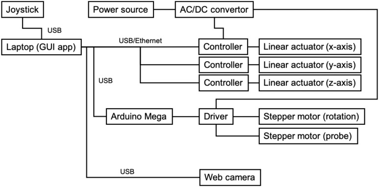
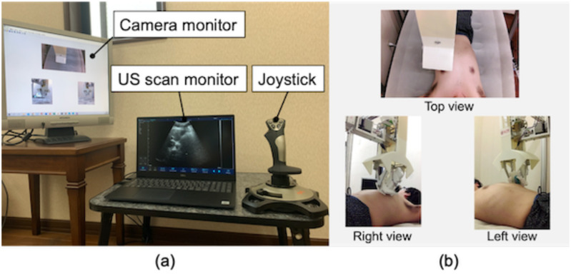
The system architecture is summarized in Fig. 6. The three linear actuators for translational motion in the positioning unit are controlled with a positioned type controller (TS-S2, Yamaha motor, Japan), which can generate pre-programmable motions to the actuators. This occurs by receiving corresponding commands via serial communication, and the stepper motors for both orientations of end-effector and probe are controlled with an associated motor driver (CVD528B, Oriental motor, Japan) via a sequential pulse generated by a universal microcontroller (Arduino Mega, Arduino, Italy). As for the robot operation interface, a joy-stick gaming controller (PXN-2113-SE, PXN, Japan) equipped with four-axis control and twelve programmable buttons was utilized in terms of the intuitive and straightforward operation for the operator. We implemented two modes for the robot operation. The first mode, called each axis control mode, controls x-, y-, z-axis translations and end-effector and probe orientations individually. Tilting the joystick controller right-and-left and back-and-forward are assigned to the x- and y-axis motions, respectively. Other axes motions are assigned to the programmable buttons. The second mode, called arc motion mode, generates the arc motion around the body axis for moving the US probe from the anterior to side region effectively. In this mode, the y- and z-axis translations and the end-effector orientation are performed simultaneously when tilting the joystick controller only right-and-left. In short, each axis control mode is utilized when searching for adequate US images in each anterior, side, and posterior region, while the arc motion mode is utilized when shifting the scan region. The platform to integrate the interface and controllers was created in Matlab (Matlab, Mathworks, USA). An overview of the control console is shown in Fig. 7. In addition, we used a wireless portable convex US probe (UProbe-C5, Sonostar, China). The US image visualization and acquisition control with the US probe can be conducted via the attached software.
Fig. 6.
System architecture overview.
Fig. 7.
(a) Operational console overview and (b) web camera view to monitor the robot and interact with the patient.
E. Experimental Testing Protocol
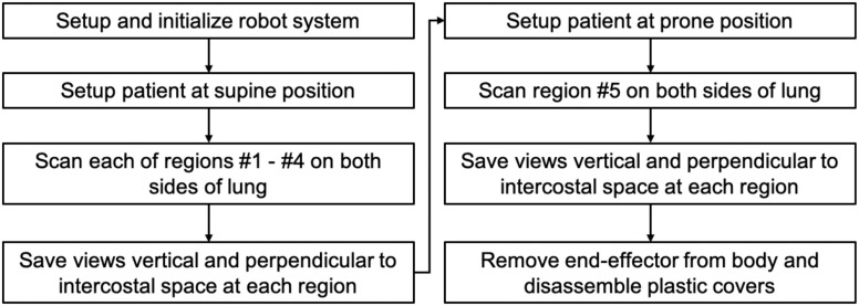
The testing protocol of the robotic LUS operation is summarized in Fig. 8. Initially, the robotic platform is transported to the location of the patient. The operator sets the US probe at the end-effector and locates the end-effector to an initial position where it does not interfere with transporting the patient to the bed. These operations are completed while the patient is being prepared for the procedure outside the US imaging station. After the preparation, the patient is moved to the imaging station and placed on the bed in the supine position. The patient applies US gel on the chest as directed. During the scan phase, the operator moves the US probe to each standardized spot as indicated in the modified BLUE protocol, collecting sequential US images until completion of the protocol. Fig. 1 shows the ten (5 × 2 planes) spots examined using the modified BLUE protocol. First, the end-effector holding the US probe is moved to spot #1 of the right side without contact with the patient. The US probe is placed on the chest and then moved downward until the passive mechanism along the z-axis direction is activated. The operator searches for the diagnostic US image that is characteristic of normal or abnormal LUS features such as a pleural line, A-lines, B-lines, or lung sliding by adjusting the end-effector position. The angle of the US probe is fixed parallel to the y-axis during the scan. Once the LUS features are observed, the operator adjusts the probe angle to acquire images perpendicular and parallel to the intercostal space and records each of the views for 5 seconds. Next, the procedure is repeated in spot #2. After scanning spots #1 and #2, the operator changes the control mode from each axis control mode to the arc motion mode and moves the US probe to the chest side following the arc path. The US probe position and posture are adjusted by changing the control mode to each axis control mode. Then, the image acquisition in spots #3 and #4 are repeated. Once the scans in spots #1 through #4 are completed for the right lung, an identical protocol is repeated for the left lung. Once the supine images are completed, the patient is placed in the prone position, and spot #5 imaging of both right and left lungs are scanned as described in Fig. 8. Finally, the end-effector is removed from the body, and the plastic cover of the US probe is discarded.
Fig. 8.
Testing protocol of the robot-assisted LUS scan.
F. Experimental Setup in Humans
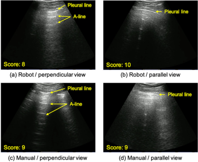
Fig. 9(a) shows the overview of the assembled robotic LUS platform. For validating the feasibility of the proposed robotic LUS platform for further human subject studies and clinical trials, 1) the operational safety and 2) acquired image quality were quantitively assessed. For evaluating the operational safety, the US probe contact force during scanning each of the regions was measured with a 6-axis force/torque sensor (Nano 17, ATI Industrial, USA). The contact force to the probe was measured for 5 seconds in each of the ten scan regions of three test subjects. This was done twice during robotic assisted operation, once during normal respiration and once during an inspiratory hold maneuver to determine the effects of respiration on image acquisition. For our reference standard, the contact force during manual scanning was measured during normal respiration. A different non-medical operator who was supervised by clinical experts (J.H., B.H.) performed both robot and manual operations for each of the three subjects. Thus, we collected 30 data sets in the robot scan under normal respiration, 30 data sets in the manual scan under normal respiration, and 30 data sets in the robot scan in the respiration hold. A sequential contact force that occurs while sliding the end-effector on the chest surface was measured; the US probe was moved from spot #1 to #2. For safety, a Visual Analog Scale (VAS) was used to monitor pain, feedback from the subjects. The subjects’ level of discomfort was measured based on an established 11-point VAS, from 0 to 10. Due to the importance of comfort and safety of the subjects, a VAS > 4 (i.e., “hurts a little”) was used as the point of termination. To quantify the acquired image quality, the acquired images were scored by the two clinical experts in the field of LUS on COVID-19 patients and collaborators on this project. The score of the image quality ranged from 0 to 10, with 0 indicating non-diagnostic quality and 10 for diagnostic superiority. The minimum score for diagnosis quality was set at 3. The criterion of the image acquisition is to observe the pleural line, A-line, and lung sliding. Fig. 10 shows representative images scored by the experts. Additionally, the contrast-to-noise ratio (CNR) of the pleural line to its surrounding area was calculated. The CNR is defined as:
 |
where μi and μo are the means of the pixel value of the region of the pleural line and background, respectively, and σi and σo represent the standard deviation of them. Fig. 9(b) shows the experimental setup overview. The bed size and its configurations are based on those commonly used in the hospital setting (height: 75 cm). The procedure followed the protocol outlined in Section II-E. Two images (parallel and perpendicular views) in ten scan spots were acquired once to each of the three subjects. As the ground truth, those images were also acquired by the manual operator following the same protocol and scored with the same criterion. For each of the three subjects, a different non-medical operator who was supervised by the clinical experts performed both robot and manual scanning; obtaining and evaluating 60 images in the robot operation and 60 images in the manual operation. In addition, the total durations of the scan time was compared. To eliminate the physician reviewer bias, the US images acquired by both robot and manual operations were assigned randomly, and the assignment was blinded to the readers. A two-tailed student t-test with a 90% confidence interval was used to determine if there were significant differences in the performance between robot-assisted and manual operations. Assuming the collected data was independent between those operations, it was normally distributed by Kolmogorov–Smirnov test. A p-value <0.05 was statistically significant. All statical analysis was performed using Matlab 2019 Statistics and Machine Learing Toolbox (Matlab, Mathworks, USA).
Fig. 9.
(a) Overview of the assembled LUS platform (b) Experimental setup overview.
Fig. 10.
(a--d) Examples of acquired images with the robot-assisted US and manual operator. Note the expected US reflectors were clearly identified by both methods.
G. Human Subjects and IRB Approval
The study was approved by the institutional research ethics committee at the Worcester Polytechnic Institute (No. IRB-21-007), and written informed consent was given by the subjects prior to all test sessions. Three subjects were enrolled in the study (see Table II).
TABLE II. Subject Information.
| Subject 1 | Subject 2 | `Subject 3 | |
|---|---|---|---|
| Age (yr) | 30 | 25 | 58 |
| Sex (M/F) | M | M | M |
| Height (cm) | 168 | 162 | 164 |
| Weight (kg) | 67 | 55 | 63 |
| Chest depth (cm) | 318 | 305 | 315 |
| Chest width (cm) | 315 | 298 | 308 |
| Chest height (cm) | 205 | 195 | 203 |
III. Results
A. Operational Safety
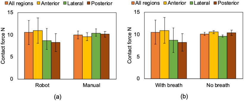
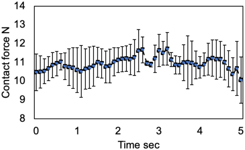
This experiment aims to validate operational safety by evaluating the contact force between the US probe and body surface. We assumed that the contact force of 20 N was acceptable according to the previous studies [13]–[18]. Fig. 11 shows the mean contact force during the scan on each of the regions. The mean contact force in all regions measured by the human and robot-assisted operations during normal respiration was 9.52 ± 1.02 N vs. 10.48 ± 2.72 N; (p = 0.55), respectively. These results suggest there was no significant contact force difference between the human and robot-assisted platform. The mean contact force in all regions measured by the robot-assisted operation during breath-hold was 10.13 ± 0.38 N. This is well under the maximal predicted threshold of 20 N. While there was no significant difference between each of those conditions, the standard deviation under the condition of robot-assisted operation allowing the subjects to breathe was large compared to other conditions. Fig. 12 shows the sequential contact force during the scan on the chest surface from spot #1 to #2. Although the contact force during the sequential scan fluctuated corresponding to the scan position, it was maintained within a specific range. Note that there was no report of greater than 4 points on the VAS in all patients.
Fig. 11.
Mean contact force on each of the ten scan regions (a) comparing the robot-assisted and manual operations under the normal respiration and (b) in the robot-assisted operation comparing under the normal respiration and breath hold. The definition of region is shown in Fig. 1.
Fig. 12.
Time-series sequential contact force during the scan on the chest surface from region #1 to #2.
B. Image Quality
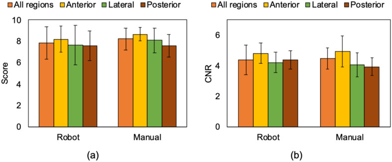
This experiment aimed to compare and validate the image quality acquired by the robot-assisted and manual operations by expert scoring and by measuring CNR of the pleural line, the primary feature of LUS. Fig. 13(a) shows the mean scores of the acquired image quality with robot-assisted and manual operations. Regional mean scoring in the robot-assisted and manual operations was 7.85 ± 1.54 vs. 8.21 ± 1.04; (p = 0.12). These results suggest there was no significant difference in terms of the visibility of lung features. The acquired images with the robot-assisted operation successfully captured the pleural line and A-line, which are representative signs for healthy lung, as shown in Fig. 10(a). Fig. 13(b) shows the result of CNR of the pleural line captured in the acquired images. The mean CNR in the robot-assisted and manual operations was 4.38 ± 0.95 vs. 4.48 ± 0.70; (p = 0.51), respectively, demonstrating no significant difference. As expected, there was a statistical difference in the robot-assisted operation's total procedure time compared to the manual operation (27.5 ± 5.4 min vs. 18.2 ± 3.2 min; p < 0.05) because the visibility of the procedure in robot scanning is limited by the field of views through the web cameras.
Fig. 13.
(a) Mean expert reader scores and (b) mean CNRs of pleural line captured in the US image acquired by the robot-assisted and manual operations. The definition of region is shown in Fig. 1.
C. Discussion
The results of this feasibility study demonstrated the safety and efficacy of a novel tele-operative robotic LUS scan platform that could be applied in humans. The robotic platform enables the successful acquisition of LUS diagnostic images in all ten scan spots of the modified BLUE protocol. Notably, all ten spots were successfully imaged while maintaining adequate contact force. The contact force was approximately 10 N, never exceeding 15 N, which confirms patient safety. This is well under the safety limits of contact force reported in the literature [14]–[18], which ranged from 20 to 24 N. No significant pain or discomfort was reported from the subjects during scanning on both platforms, as demonstrated by a VAS score of <4. The combined contact force and pain level the subjects experienced were acceptable when identifying quality imaging of the diagnostic features of LUS. While, the contact force variation during the robot operation was confirmed. The variation is reflected in the subject respiration. In the manual operation, the probe position can be finely adjusted depending on the displacement of the body surface due to respiration with the force feedback for the hand so that the contact force's variation is comparably small. The passive-actuated end-effector with the constant force spring can also absorb the displacement theoretically. Nevertheless, the constant force spring may not respond to the small variation of the spring displacement depending on the extension length of the spring due to its intrinsic characteristics [20]. While the passive end-effector design and manufacturing can be improved, we believe current contact force variation (2.72 N) is acceptable, based on the force variation (11.6 ± 2.47 N) in the manual fetal scan operated by sonographers as previously reported [21].
The total cost to build the prototype system was approximately 10000-15000 USD. We expect further cost reduction is feasible as a final product for clinical use. While the linear actuators in our system are commercially available, they were purchased at market price and not in a bulk manner as would be applied to production models. As the end-effector designed in this paper is one-of-a-kind, the manufacturing cost was by necessity, increased. If we moved to production, economy of scale would allow for a truly low-cost iteration. Also, we assume there is a potential cost reduction in terms of an education for sonographers. If the system can be deployed, one expert sonographer has the capability to perform the diagnosis in myriad locations. Sonographers typically spend several years in training, and this education is generally more costly than the actual robotic system. In addition, the proposed hybrid configuration is expected to shorten the learning-curve for the operation, since the height position and angle of the ultrasound probe are adjusted automatically with the passive-mechanism. The operators only need to control the position in transverse and longitudinal directions basically.
IV. Limitations
A significant limitation of the proposed platform is that we cannot perform fine adjustment of US probe alignment and contact force actively. The proposed end-effector orients the US probe normal to the body surface independent of the scan positions. While the robot-assisted operation captured the pleural line in all scan regions, lung artifact such as A-lines were not always visible due to the lack of rotation adjustment. Given that a manual operator needs to adjust the US probe orientation finely to obtain such features clearly, additional actuators for rotation may be implemented into the end-effector. Furthermore, when acquiring US images in patients with excessive subcutaneous tissue, the manual operator often applies additional force to the US probe. Consequently, the contact force applied by the end-effector need adjustments based on patient body habitus.
Another limitation is the lack of validation and cross-validation of other imaging modalities in COVID-19 patients. Several pathological features, including the disappearance of lung sliding, increased lung artifact B-lines, and lung consolidation, cannot be evaluated in healthy subjects. Before implementing the platform for the study of COVID-19, we recognize it is necessary to perform a comparative study on a larger number of subjects with non-COVID-19 related lung disease. Such subjects might include those with a variation in body surface area, obesity, and female subjects. Additional improvements in hardware design must be taken into account. Because the procedure to apply US gel to the thorax is still manual, this confers a potential risk of infection transmission. Future prototypes might include a gel-dispenser incorporated into the end-effector or by utilizing single-use gel packets. Notably, the challenges that may arise with decontaminating the equipment between US studies need to be addressed. A simple decontamination approach for both the end-effector and the moving arm would be protected with transparent plastic covers similar to a conventional surgical robot. The cover used for the US probe has no known acoustic impedance mismatch or degradation of the transmitted US beam or effect on the image quality. Additionally, the part touching the patient body, such as the tip of the end-effector or the end-effector itself, should be modified to be detachable for replacing it for every study. The rest of the other frame parts not protected with the disposable cover should be protected with non-porous, chemical-proof hard-cover, such as polyether ether ketone in order to prevent the aerosol from penetrating the frame parts.
The American Institute of Ultrasound Medicine has proposed current guidelines for cleaning and preparing external use ultrasound transducers and equipment between patients, and safe handling and use of ultrasound gel. [22] These guidelines include the latest changes due to the COVID-19 outbreak that are based on the recent Centers for Disease Control and Prevention guidelines [23], which report the current level of disinfection for external devices such as US procedures, requires low-level disinfection, not sterilization, as acceptable. Therefore, sterilization or a covering of the US probe and end-effector may not be necessary. Contact precautions in COVID-19 are ever-evolving and would be adapted accordingly. Lastly, the gantry's portability would be of significant benefit, as the system could be moved to the patient, further mitigating the spread of infection.
Additional applications of this robot system include lung diseases similar to COVID-19. Moreover, there is a potential application for imaging and diagnosis of various organ systems and anatomic structures, including hepatobiliary, renal, and abdominal aortic ultrasounds. Even in a well-resourced country such as the United States, there are many rural areas where US availability is limited or not available, and having the ability to perform a scan remotely could be a significant benefit.
V. Conclusion
This manuscript presents a feasibility study of applying a tele-operative robotic platform on human subjects for the application of LUS. Our preliminary results demonstrate that the proposed platform enables the successful acquisition of diagnostic images with a safe contact force at all standardized scan spots using the modified BLUE protocol. The robotic LUS platform has the potential to be applied to COVID-19 and other infectious diseases. The use of this technology may reduce the risk of disease transmission among patients and healthcare workers in a resource-limited environment by minimizing the physical contact during the US procedure.
Acknowledgment
The authors would like to thank Yamaha Motor, Co. Ltd., Ono-denki, Corp., Sonostar Technologies, Co. Ltd, Kyocera, Corp., Dr. Y. Uchida, Dr. CJ. Nycz, and Mr. JT. Kaminski for assisting this project.
Funding Statement
This work was supported by the National Institute of Health (DP5 OD028162)
Contributor Information
Ryosuke Tsumura, Email: rtsumura@wpi.edu.
John W. Hardin, Email: jhardin@bidmc.harvard.edu.
Keshav Bimbraw, Email: bimbrawkeshav@gmail.com.
Anne V. Grossestreuer, Email: agrosses@bidmc.harvard.edu.
Olushola S. Odusanya, Email: sodusanya@aust.edu.ng.
Yihao Zheng, Email: yzheng8@wpi.edu.
Jeffrey C. Hill, Email: jeffrey.hill@mcphs.edu.
Beatrice Hoffmann, Email: bhoffma2@bidmc.harvard.edu.
Winston Soboyejo, Email: wsoboyejo@wpi.edu.
Haichong K. Zhang, Email: hzhang10@wpi.edu.
References
- [1].Johns Hopkins Univ., Coronavirus Resource Center: Daily Summary. 2021, Acceessed: Jan. 9, 2021. [Online]. Available: https://coronavirus.jhu.edu/ [Google Scholar]
- [2].Fang Y. et al. , “Sensitivity of chest CT for COVID-19: Comparison to RT-PCR,” Radiology, vol. 296, no. 2, pp. E115–E117, 2020. [DOI] [PMC free article] [PubMed] [Google Scholar]
- [3].Xia Y., Ying Y., Wang S., Li W., and Shen H., “Effectiveness of lung ultrasonography for diagnosis of pneumonia in adults: A systematic review and meta-analysis,” J. Thorac. Dis., vol. 8, no. 10, pp. 2822–2831, 2016. [DOI] [PMC free article] [PubMed] [Google Scholar]
- [4].Ayebare R. R., Flick R., Okware S., Bodo B., and Lamorde M., “Adoption of COVID-19 triage strategies for low-income settings,” Lancet Respir. Med., vol. 8, no. 4, pp. e22, 2020. [DOI] [PMC free article] [PubMed] [Google Scholar]
- [5].Manivel V., Lesnewski A., Shamim S., Carbonatto G., and Govindan T., “CLUE: COVID-19 lung ultrasound in emergency department,” EMA - Emerg. Med. Australas., vol. 32, no. 4, pp. 694–696, 2020. [DOI] [PMC free article] [PubMed] [Google Scholar]
- [6].Moore S. and Gardiner E., “Point of care and intensive care lung ultrasound: A reference guide for practitioners during COVID-19,” Radiography, vol. 26, no. 4, pp. 297–e302, 2020. [DOI] [PMC free article] [PubMed] [Google Scholar]
- [7].Soldati G. et al. , “Proposal for international standardization of the use of lung ultrasound for patients with COVID-19: A simple, quantitative, reproducible method,” J. Ultrasound Med., pp. 1413–1419, 2020. [DOI] [PMC free article] [PubMed]
- [8].Lichtenstein D. A., “BLUE-Protocol and FALLS-Protocol: Two applications of lung ultrasound in the critically ill,” Chest, vol. 147, no. 6, pp. 1659–1670, 2015. [DOI] [PubMed] [Google Scholar]
- [9].Peng Q. Y., Wang X. T., and Zhang L. N., “Findings of lung ultrasonography of novel corona virus pneumonia during the 2019–2020 epidemic,” Intensive Care Med , vol. 46, no. 5, pp. 849–850, 2020. [DOI] [PMC free article] [PubMed] [Google Scholar]
- [10].Amatya Y. et al. , “Diagnostic use of lung ultrasound compared to chest radiograph for suspected pneumonia in a resource-limited setting,” Int. J. Emerg. Med. , vol. 11, no. 8, pp. 1–5, 2018. [DOI] [PMC free article] [PubMed] [Google Scholar]
- [11].Priester A. M., Natarajan S., and Culjat M. O., “Robotic ultrasound systems in medicine,” IEEE Trans. Ultrason. Ferroelectr. Freq. Control, vol. 60, no. 3, pp. 507–523, 2013. [DOI] [PubMed] [Google Scholar]
- [12].Swerdlow D. R., Cleary K., Wilson E., Azizi-Koutenaei B., and Monfaredi R., “Robotic arm-assisted sonography: Review of technical developments and potential clinical applications,” Am. J. Roentgenol., vol. 208, no. 4, pp. 733–738, 2017. [DOI] [PubMed] [Google Scholar]
- [13].Ye R. et al. , “Feasibility of a 5G-Based robot-assisted remote ultrasound system for cardiopulmonary assessment of patients with COVID-19,” Chest, vol. 159, no. 1, pp. 270–281, 2021. [DOI] [PMC free article] [PubMed] [Google Scholar]
- [14].Tsumura R., and Iwata H., “Robotic fetal ultrasonography platform with a passive scan mechanism,” Int. J. Comput. Assist. Radiol. Surg., vol. 15, no. 8, pp. 1323–1333, 2020. [DOI] [PubMed] [Google Scholar]
- [15].Burcher M. R., Noble J. A., Han L., and Gooding M., “A system for simultaneously measuring contact force, ultrasound, and position information for use in force-based correction of freehand scanning,” IEEE Trans. Ultrason. Ferroelectr. Freq. Control, vol. 52, no. 8, pp. 1330–1342, 2005. [DOI] [PubMed] [Google Scholar]
- [16].Dhyani M. et al. , “A pilot study to precisely quantify forces applied by sonographers while scanning: A step toward reducing ergonomic injury,” Work, vol. 58, no. 2, pp. 241–247, 2017. [DOI] [PubMed] [Google Scholar]
- [17].Gilbertson M. W. and Anthony B. W., “Force and position control system for freehand ultrasound,” IEEE Trans. Robot., vol. 31, no. 4, pp. 835–849, 2015. [Google Scholar]
- [18].Delgorge C. et al. , “A tele-operated mobile ultrasound scanner using a light-weight robot,” IEEE Trans. Inf. Technol. Biomed., vol. 9, no. 1, pp. 50–58, 2005. [DOI] [PubMed] [Google Scholar]
- [19].Kouchi M. and Mochimaru M., “Japanese 3-D body shape and dimensions data 2003,” Natl. Inst. Adv. Ind. Sci., H18PRO503, 2003.
- [20].Ohtsuki A., Oshima S., and Itoh D., “Analysis on characteristics of a C-Shaped constant-force spring with a guide,” JSME Int. J. Ser. C, vol. 44, no. 2, pp. 494–499, 2001. [Google Scholar]
- [21].Tsumura R. and Iwata H., “Development of ultrasonography assistance robot for prenatal care,” Proc. SPIE Med. Imag., vol. 11315, pp. 1131520, 2020. [Google Scholar]
- [22].The American Institute of Ultrasound Medicine, Guidelines For Cleaning and Preparing External- and Internal-Use Ultrasound Transducers and Equipment Between Patients as Well As Safe Handling and Use of Ultrasound Coupling Gel, 2020, [Online]. Available: https://www.aium.org/officialstatements/57, Acceessed: Jan. 9, 2021. [DOI] [PubMed] [Google Scholar]
- [23].National Center for Immunization and Respiratory Diseases, Environmental Cleaning and Disinfection Recommendations, 2020. [Online]. Available: https://www.cdc.gov/coronavirus/2019-ncov/community/organizations/cleaning-disinfection.html, Acceessed: Jan. 19, 2021. [Google Scholar]
- [24].Gullett J. et al. , “Interobserver agreement in the evaluation of B-lines using bedside ultrasound,” J. Crit. Care., vol. 30, no. 6, pp. 1395–1399, 2015. [DOI] [PubMed] [Google Scholar]


