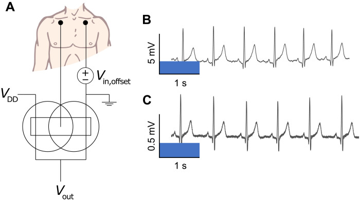
Fig. 3. ECG signal amplification using cofacial pair complementary inverter.
(A) The wiring diagram of the cofacial pair inverter when used as a voltage preamplifier. 3M adhesive medical electrodes are placed below the clavicle on both the right and left side, with one being connected to a DC offset and the other connected directly to the input of the inverter on a benchtop. (B) The ECG signal recorded from the output of the cofacial pair inverter. (C) The ECG signal recorded directly between the adhesive medical electrodes using a benchtop DMM.

