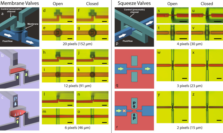
Fig. 1. 3D printed membrane valves and squeeze valves.
a Schematic diagram of membrane valve geometry with cut-away schematics showing a membrane valve in (b) open and (c) closed states depending on pneumatic pressure applied through the control channel. d–o Side- and top-view microscope images of (d–g) 20 pixel, (h–k) 12 pixel, and (l–o) 6 pixel diameter valves in their open and closed states. p Schematic diagram of squeeze valve geometry with cross-section diagrams (rotated 90∘) showing a squeeze valve in (q) open and (r) closed states depending on pneumatic pressure applied through the control channel, which squeezes together to close the flow channel. s–z Microscope images of (s–v) 4 × 4 pixel (side- and top-view), (w,x) 3 × 3 pixel (top-view), and (y,z) 2 × 2 pixel (top-view) valves in their open and closed states. All scale bars are 100 μm.

