. 2021 Sep 6;10:e69310. doi: 10.7554/eLife.69310

Figure 2. Schematic design and strain characterization of the aorta smooth muscle-on-a-chip model.

(a) Schematic overview of the in vitro chip model. (b) Cross-sectional view of the microfluidic aorta smooth muscle-on-a-chip model showing the deformations of the PDMS membranes under different vacuum pressures. The scale bar represents 5 mm. (c) Measured tensile strains of the upper (red) and lower (blue) membranes at negative pressures of 10 kPa and 15 kPa for five cycles. The peak tensile strain per cycle averaged 7.18 ± 0.44% with a cyclic negative pressure of 10 kPa and 17.28 ± 0.91% with a cyclic negative pressure of 15 kPa.

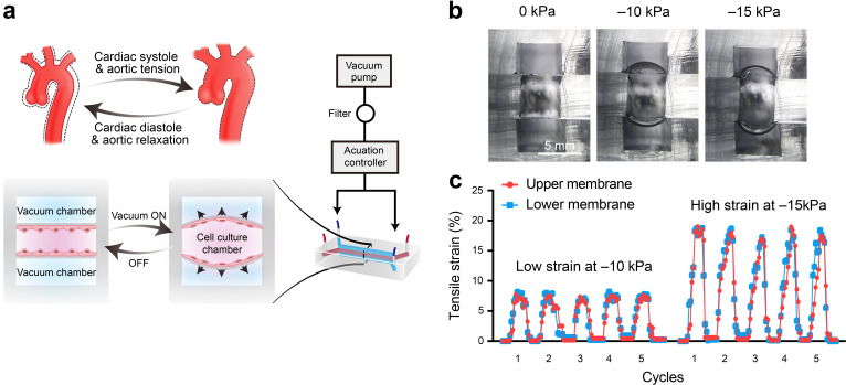
Figure 2—source data 1. The quantification data for measurement of tensile strains of the upper and lower membranes.

Figure 2.

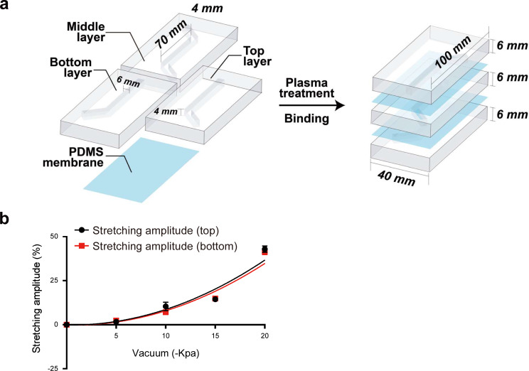
Figure 2—figure supplement 1. Characterization and parameters of the aorta smooth muscle-on-a-chip model.

Figure 2—figure supplement 1.

(a) Assembly and parameters of the PDMS aorta-on-a-chip model. (b) Membrane deformation under different vacuum pressures (0 kPa, 10 kPa, 15 kPa, and 20 kPa).
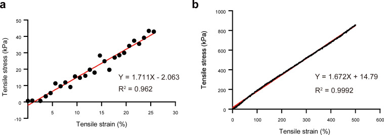
Figure 2—figure supplement 2. Tensile stress–strain responses of PDMS membrane.

Figure 2—figure supplement 2.

(a) Tensile strains of 25%. (b) Tensile strains of 500%.
Figure 2—figure supplement 2—source data 1. The raw data of Tensile stress–strain responses of PDMS membrane.
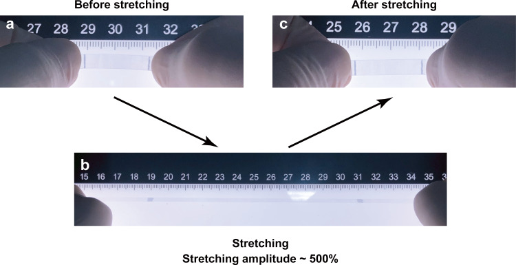
Figure 2—figure supplement 3. The photographs of a piece of highly (500%) stretched PDMS membrane.

Figure 2—figure supplement 3.

The photographs of a piece of PDMS membrane before stretching (a), 500% elongation (b), recovered PDMS membrane (c) after 500% stretching.
Figure 2—animation 1. Cross-sectional deformation of the PDMS membranes in the microfluidic chip with a 2 mm culturing channel, at the cyclic pressure of -10 kPa.
Figure 2—animation 2. Cross-sectional deformation of the PDMS membranes in the microfluidic chip with a 2 mm culturing channel, at the cyclic pressure of -15 kPa.
Figure 2—animation 3. Cross-sectional deformation of the PDMS membranes in the microfluidic chip with a 4 mm culturing channel, at the cyclic pressure of -10 kPa.
Figure 2—animation 4. Cross-sectional deformation of the PDMS membranes in the microfluidic chip with a 4 mm culturing channel, at the cyclic pressure of -15 kPa.
Figure 2—animation 5. Cross-sectional deformation of the PDMS membranes in the microfluidic chip with a 6 mm culturing channel, at the cyclic pressure of -10 kPa.
Figure 2—animation 6. Cross-sectional deformation of the PDMS membranes in the microfluidic chip with a 6 mm culturing channel, at the cyclic pressure of -15 kPa.