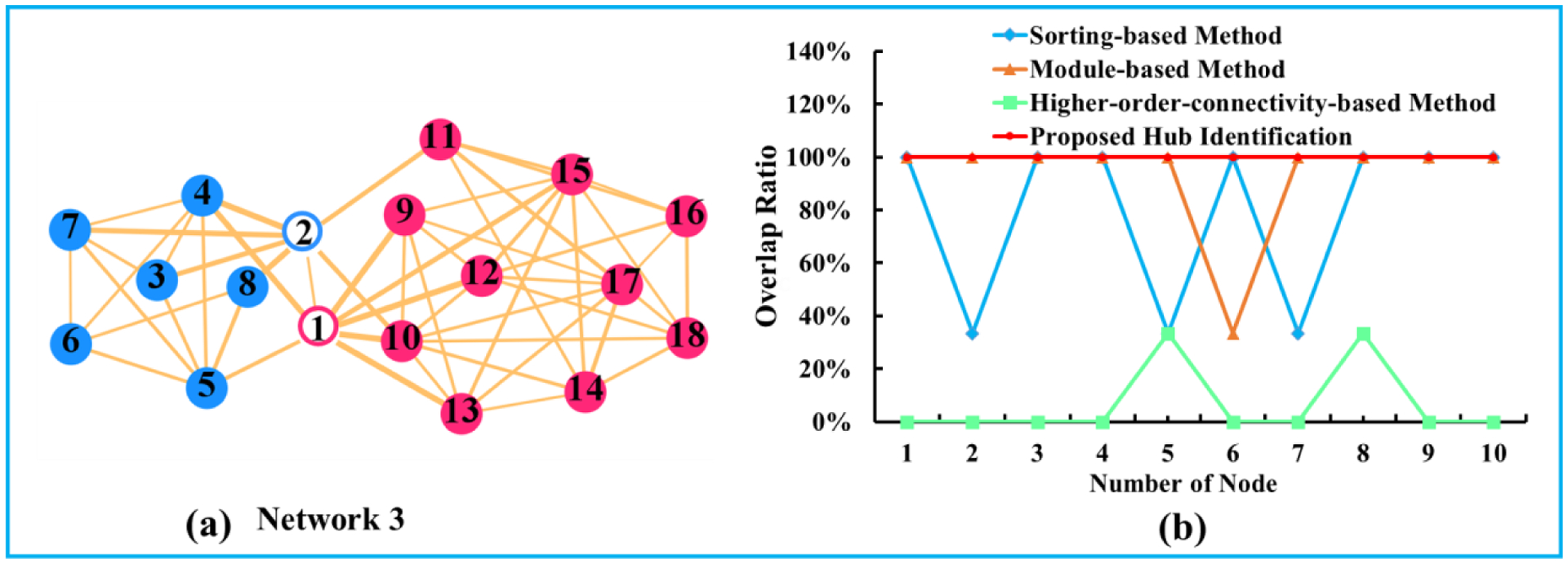
Fig. 4.

(a) is the baseline network model, in which the connector hub nodes are fixed. Red and blue designate the module information. Hollow and solid circle respectively represent the ground truth of connector hub and non-connector hub. (b) Overlap ratio between the estimated hub nodes and the ground truth hub nodes by the sorting-based method (blue), the module-based method (orange), higher-order-connectivity-based method (green), and our joint hub identification method (red).
