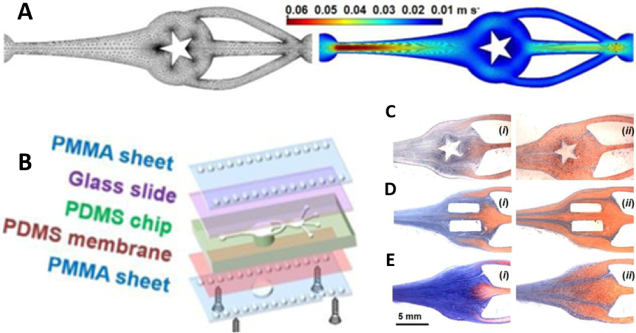
Figure 19. Microfluidic Bioprinting.

(A) Schematic diagram of the microfluidic chip with four inlets and one shared outlet.
(B) A model of the closed chamber under sinusoidal fluid flow, and images (C-E) demonstrating the role of mixing and washing of streamline flow in GelMA solution, with a star pattern or two rectangular patterns vs. no pattern. (Reprinted with permission from ref264. Copyright 2018 Advanced Materials).
