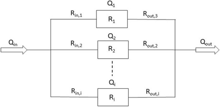
FIGURE 3.
Schematic of the fluidic resistances of an MPS in which organ chambers are arranged in parallel (Qi = flow rate through chamber i. Δp = pressure drop across the channel/chamber segments. Rin,i = hydraulic resistances of inlet channel i. Ri = hydraulic resistance of organ chamber i. Rout,i = hydraulic resistance of outlet channel i.).

